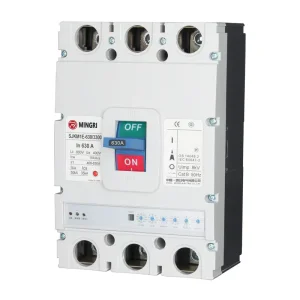
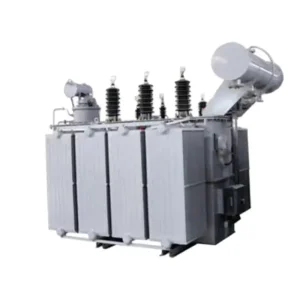
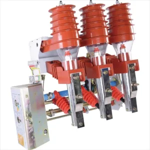
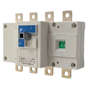
Featured Industrial Power Switching & Substation Systems
Explore our top-tier switchgear, automated transfer switches, and integrated medium-to-low voltage apparatus built for mission-critical American and global distribution architectures.
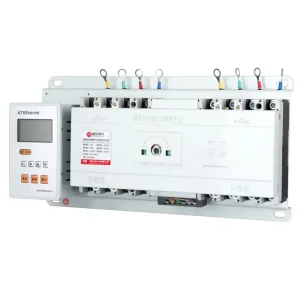
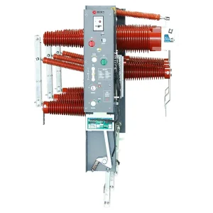
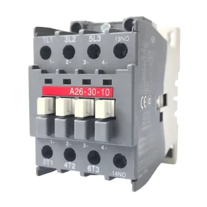
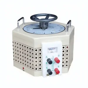
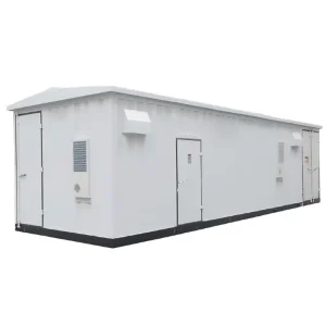
Engineering Taxonomy: The American-Style Box Substation
Understanding structural integration, internal oil-immersed topologies, safety interlocks, and design paradigms that separate American pad-mounted substations from European modular variants.
The American Style Box Substation (commonly classified within North American engineering circles as a pad-mounted compartmented distribution transformer unit or integrated pad-mount substation) represents a critical milestone in electrical distribution engineering. Unlike European-style prefabricated substations (e.g., YB series) which house distinct walk-in medium-voltage switchgear rooms, separate dry-type or oil transformer enclosures, and low-voltage distribution compartments under an expansive walk-in or non-walk-in structural canopy, the American style substation utilizes a streamlined, single-tank integration methodology.
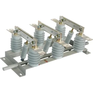
In the classic American pad-mount topology (often designated as the ZGS series in international procurement), the transformer active core and coil assembly, high-voltage multi-position load break switch (two-position or four-position loop feed switch), and protective backup and bayonet expulsion fuse assemblies are completely submerged inside the transformer dielectric fluid tank. This liquid-immersed internal configuration delivers dramatic physical compaction, exceptionally high heat dissipation coefficients, and intrinsic protection from environmental elements such as marine salt fog, industrial chemical particulates, high ambient humidity, and seismic oscillations.
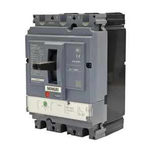
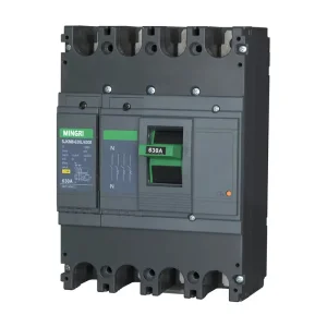
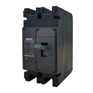
Terminations on the primary medium-voltage side are engineered according to IEEE 386 dead-front separable insulated connector standards. This eliminates exposed live conductors, guaranteeing absolute touch-safe protection for operating personnel and public spaces. The secondary low-voltage side features dedicated molded case circuit breakers (MCCB), intelligent electronic devices (IEDs), power quality metering, and transient surge suppression, segregated in a side-by-side or front-to-back tamper-resistant outdoor steel enclosure constructed in accordance with ANSI/IEEE C57.12.28 enclosure integrity mandates.
Why Tier-1 Global Utilities Partner With China OEM Manufacturers
From raw grain-oriented electrical silicon steel slitting to robotic automated tank welding and comprehensive laboratory dielectric verification.
End-to-End Vertical Supply Chain
Located in primary electrical manufacturing clusters like Yueqing, Zhejiang, our factories leverage deeply integrated component ecosystems. Every critical subsystem—from high-grade low-loss laser-treated silicon steel cores, oxygen-free electrolytic copper winding wires, and vacuum epoxy bushings to vacuum circuit breakers and microcomputer protection units—is sourced and assembled within an optimized logistics radius.
- Shorter production cycle: 4-6 weeks vs. 20+ weeks in western markets
- Direct procurement leverage lowering overall capital expenditure (CapEx)
- In-house tank fabrication with automated CNC laser cutting & robotic welding
Rigorous QA/QC & Full Type Testing
China OEM manufacturers adhere strictly to ISO 9001, ISO 14001, and ISO 45001 management architectures. Routine tests and type tests are performed in state-of-the-art testing bays, ensuring compliance with IEEE C57.12.00, IEEE C57.12.28, IEEE C57.12.34, and IEC 62271-202 specifications.
- Full lightning impulse withstand testing (BIL up to 200 kV)
- Partial discharge (PD) testing guaranteed < 10 pC at rated voltage
- Helium mass spectrometer leak testing for sealed liquid tanks
Tailored Engineering & Custom ODM
Global electrical contractors face varying utility interconnection codes. Our dedicated design engineering team provides 3D CAD parameterization, finite element thermal simulations, and transient short-circuit calculations to engineer custom substations that drop directly onto existing concrete pads without site redesign.
- Dual-voltage configuration (e.g., 13.8 kV / 24.94 kV delta-wye switching)
- Option for natural ester (FR3) vegetable fluid for high fire-safety zones
- Customized control compartment layouts for customer-specified SCADA relays
Technological Mega-Trends Driving Substation Evolution
How digitalization, eco-friendly dielectrics, and grid decarbonization are transforming American-style distribution hardware.
Biodegradable Ester Fluids & Eco-Dielectrics
While conventional mineral oil has dominated for decades, modern box substations increasingly implement high-fire-point natural ester fluids (K-class, flash point > 300°C). This allows installation in dense urban centers, commercial retail envelopes, and zero-clearance building vicinities without expensive deluge water-spray firewalls, while boasting 100% biological degradability in water and soil.
Intelligent IoT Sensing & Edge Telemetry
Modern OEM substations incorporate smart edge monitoring suites: fiber-optic real-time transformer winding temperature sensors, continuous dissolved gas analysis (DGA), electronic pressure relief sensors, and automated low-voltage feeder load management. Data streams link natively via DNP3.0, Modbus TCP/IP, or IEC 61850 protocol to cloud dashboards or municipal SCADA.
Amorphous Alloy Low-Loss Cores
To comply with increasingly stringent Tier-2 efficiency standards (such as US DOE 2016 and EU Ecodesign 2021), advanced box substations deploy amorphous alloy ribbons in place of conventional silicon steel cores. This slashes transformer no-load core losses by an astounding 60% to 75%, generating immense long-term lifecycle OPEX savings for grid operators.
Mission-Critical Deployment Scenarios
Proven engineering architectures engineered for harsh physical environments, high-cycling renewable feeding, and continuous commercial power.
Utility-Scale Solar PV & BESS Step-Up
In utility solar farms and Battery Energy Storage Systems (BESS), American box substations act as skid-mount or pad-mounted inverter step-up stations (e.g., boosting 690V or 800V inverter outputs directly to 13.8kV, 24.94kV, or 34.5kV collector lines). Units feature electrostatic shielding between primary and secondary windings to mitigate inverter carrier frequency harmonics.
Ultrafast EV Fleet Hubs & Microgrids
High-power megawatt DC fast-charging depots impose severe load fluctuations. Our substations incorporate heavy-duty low-voltage copper busbar systems, transient harmonic mitigation filters, dynamic power factor correction modules, and high-cycling MCCBs designed to withstand thermal cycling caused by rapid EV battery ramp-up events.
Commercial Campuses & High-Density Real Estate
For corporate office developments, medical centers, and university facilities, aesthetic integration and whisper-quiet acoustic footprints are critical. American-style units can be finished in bespoke powder-coated architectural hues (RAL palettes) with sound dampening cores achieving operational noise thresholds well below 50 dB(A).
Engineering Matrix: American-Style vs. European-Style Substations
A granular comparison guide for EPC consultants, electrical specifying engineers, and global procurement managers.
| Evaluation Parameter | American-Style Box Substation (Pad-Mounted) | European-Style Prefabricated Substation |
|---|---|---|
| Integration Philosophy | Single-tank integrated structure; core, windings, MV switch, and fuses fully submerged in liquid dielectric. | Modular multi-compartment structure; separate MV switchgear room, transformer chamber, and LV panel board. |
| Physical Footprint | Ultra-compact footprint; typically occupies 1/3 to 1/2 of the ground space required by European units. | Larger dimensional footprint; accommodates internal walk-in service aisles or deep compartment housings. |
| Primary MV Protection | Internal dual-fuse philosophy: Bay-O-Net expulsion fuse in series with Current-Limiting backup fuse. | External MV switchgear using SF6/solid/air Ring Main Unit (RMU) with Vacuum Circuit Breaker or Fuse-switch. |
| Dead-Front Safety | 100% Dead-Front construction standard via IEEE 386 elbow connectors; zero exposed live metal in MV bay. | Live-front or dead-front options within enclosed metal switchgear cabinets. |
| Cooling / Enclosure Class | ONAN / KNAN natural fluid convection inside corrugated or radiator tank; IP54/NEMA 3R outdoor steel tank. | Air natural (AN) or forced air cooling (AF) within ventilated enclosure shells; IP33 to IP43 typical. |
| Primary Target Applications | Underground residential distribution (URD), solar farms, EV charging hubs, commercial retail pads. | Urban municipal grids, industrial heavy manufacturing facilities, mining complexes, metro rail step-down. |
Global EPC Procurement Matrix: Specifying Substation Projects
Essential engineering parameters required when requesting OEM proposals from Chinese manufacturers.
1. Electrical Grid Parameters
Specify nominal system voltage (e.g., 11 kV, 13.8 kV, 24.94 kV, 34.5 kV), frequency (50 Hz or 60 Hz), vector group configuration (Dyn11, Yyn0, etc.), Basic Impulse Level (BIL) requirements, and expected grid fault short-circuit levels (kA withstand for 1s to 3s).
2. Environmental Service Conditions
Define installation ambient conditions: minimum and maximum temperatures (-30°C to +50°C), altitude derating factors (>1000m above sea level requires expanded electrical clearances), seismic zone classifications, and atmospheric corrosivity tiers (ISO 12944 C3, C4, or C5-M for coastal projects).
3. Secondary Feeder & SCADA Specs
Provide single-line diagram (SLD) depicting outgoing low-voltage branch circuits, breaker ratings, automatic transfer switch (ATS) configurations, surge protective device (SPD) requirements, and CT/PT metering accuracies for utility billing or internal power monitoring.
Frequently Asked Questions: American-Style Box Substations
Definitive answers compiled by our application engineering and quality assurance departments.
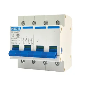
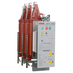
Integrated Breakers, Isolation Switches & Transformers
Browse complementary low-voltage and medium-voltage equipment manufactured for seamless integration inside turnkey distribution substations.