Primary Surge Arresters & Low-Voltage Protection Portfolio
Precision-manufactured SPDs, heavy-duty molded case circuit breakers, and automatic voltage regulation hardware engineered to mitigate high-energy atmospheric surges and internal switching transient spikes.
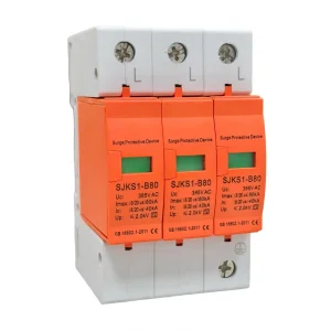
High-Quality SJKS1-B Series Surge Protection Device 80KV 385V Factories, Companies
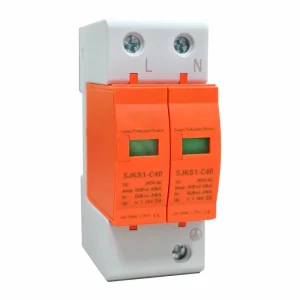
ODM SJKS1-C Series Surge Protection Device SPD 3/4P 25kA Suppliers, Company
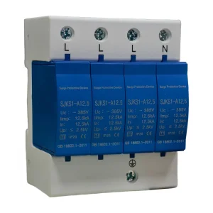
ODM SJKS1D Series Surge Protection Device 1P-4P 50Hz Manufacturers, Company
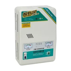
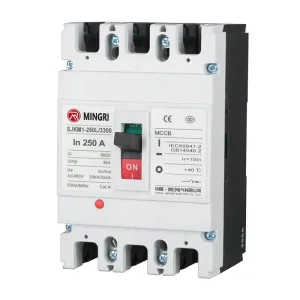
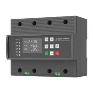
Wholesale 80/125A Economic Three-phase Current-limiting Protector Manufacturer, Company
Global Enterprise Procurement Dynamics for Surge Protection
Navigating vendor qualification, multi-tiered risk mitigation, and cascading insulation coordination within mission-critical utility and industrial power architecture.
Tier-1 Component Metallurgy & MOV Integrity
For modern EPCs and industrial procurement officers, assessing Surge Protective Device (SPD) quality begins at the semiconductor level. High-performance Metal Oxide Varistors (MOVs) rely on high-purity Zinc Oxide (ZnO) grains sintered with bismuth, cobalt, and manganese oxides. Premium manufacturers implement automated thermal imaging scans to eliminate localized micro-voids, preventing catastrophic short-circuit flashovers and degradation from recurring micro-surges.
Cascading Coordination & Energy Selectivity
Enterprise power distribution networks must enforce systematic energy coordination under IEC 62305-4. Specifiers ensure that upstream Class I / Type 1 SPDs (tested with a 10/350 μs waveform) absorb large direct lightning currents at service entrance switchgear, while downstream Class II / Type 2 devices (tested with an 8/20 μs waveform) clamp residual overvoltages at sub-distribution boards without premature trip conflicts.
Total Cost of Ownership (TCO) & Lifecycle Up-time
Specifying engineers prioritize modular, pluggable cartridge designs equipped with high-temperature micro-thermostats and remote telemetry signaling (form-C dry contacts). The ability to swap sacrificial surge suppression modules during live line conditions without interrupting primary plant operations directly reduces downtime losses in automated process manufacturing and tier-4 data centers.
Macro-Industry Engineering Solutions
Tailored surge mitigation architectures designed for severe electrical environments, extreme thermal fluctuations, and continuous industrial operations.
Solar PV & Storage
Utility-scale 1000V/1500V DC central inverters and string combiners require specialized Y-circuit surge protection configurations. These prevent insulation degradation caused by sustained DC arcs during varistor failure, ensuring safe operation during prolonged high-voltage conditions.
Hyperscale Data Centers
Modern compute facilities combine Gas Discharge Tubes (GDT) and fast MOVs in hybrid topologies to achieve ultra-low voltage protection levels ($U_p < 1.0\text{ kV}$). This protects sensitive server power supplies and microcontrollers from high-frequency switching transients.
Heavy Industrial Automation
Variable frequency drives (VFDs) and large inductive motor banks generate continuous transient ringing. Heavy-duty Class II SPDs absorb these inductive spikes directly at the Motor Control Center (MCC), protecting control PLCs from spurious resets.
Rail & Electrified Transit
Signaling installations along electrified catenaries face severe ground potential rise (GPR) and inductive lightning strikes. Coordinated multi-stage spark gap and surge diverter panels safeguard signaling interlocks and trackside communication relays.
Engineering Parameter Matrix: IEC vs. UL Classifications
Key testing parameters, wave shapes, and installation standards across major global surge protection methodologies.
| Classification Class | Test Waveform | Primary Physical Mechanism | Typical Installation Location | Core Performance Metrics |
|---|---|---|---|---|
| Class I (IEC) / Type 1 (UL) | 10/350 μs (Impulse Current $I_{imp}$) | Heavy-Duty Spark Gap / Large-Block High-Capacity ZnO MOV | Main Service Entrance Switchgear, Substation LV Incomer | $I_{imp} \ge 12.5\text{ kA} - 50\text{ kA}$, $U_p \le 2.5\text{ kV}$, Zero Follow Current ($I_{fi}$) |
| Class II (IEC) / Type 2 (UL) | 8/20 μs (Nominal Discharge $I_n$) | Metal Oxide Varistor (MOV) Arrays with Thermal Disconnect | Sub-Distribution Panels, Motor Control Centers (MCC) | $I_n \ge 20\text{ kA} - 40\text{ kA}$, $I_{max} \ge 40\text{ kA} - 100\text{ kA}$, $U_p \le 1.5\text{ kV}$ |
| Class III (IEC) / Type 3 (UL) | 1.2/50 μs Voltage & 8/20 μs Current | Fast Hybrid Circuit (MOV + TVS Diode + GDT) | Sensitive Terminal Equipment, PLC I/O, Data Cabinets | $U_{oc} \ge 6\text{ kV} - 20\text{ kV}$, $U_p \le 0.8\text{ kV} - 1.0\text{ kV}$, Clamping Time < 1 ns |
| Photovoltaic DC (IEC 61643-31) | Combined 10/350 μs & 8/20 μs DC | Y-Connected Varistor Topology with DC Arc Extinguisher | Solar Combiner Boxes, Central/String Inverter DC Inputs | $U_{cpv} = 600\text{V} / 1000\text{V} / 1500\text{V DC}$, $I_{total} \ge 40\text{ kA}$, High $I_{scpv}$ |
IoT-Enabled Smart Condition Monitoring
The industry is rapidly shifting toward intelligent SPDs equipped with built-in micro-sensing circuits. These units monitor real-time leakage current ($\mu\text{A}$), log cumulative lightning strikes, measure MOV operating temperature, and communicate via RS485 Modbus or wireless LoRaWAN directly into plant SCADA systems.
Silicon Carbide (SiC) Hybrid Matrices
Next-generation R&D incorporates wide-bandgap Silicon Carbide (SiC) semiconductors alongside traditional varistors. SiC devices offer near-instantaneous sub-nanosecond response times and virtually zero degradation from repetitive low-energy switching surges, extending equipment life in mission-critical networks.
Eco-Gas & Solid Dielectric Coordination
As utilities transition away from SF6 toward eco-friendly air and solid-insulated switchgear, surge suppressors must adapt to tighter internal clearances. Compact, hermetically sealed SPD modules prevent ionization discharges and maintain full dielectric strength up to 40.5 kV.
Localization Support & Regional Earthing Topologies
Achieving electrical compliance across varied grounding schemes: TN-S, TN-C-S, TT, and isolated IT networks worldwide.
Earthing Scheme Optimization
Different grounding topologies require specific SPD pole configurations:
- TN-C Systems: 3P configurations (L1, L2, L3 to PEN).
- TN-S Systems: 4P configurations with dedicated protection for neutral and protective earth.
- TT Systems: "3+1" (N-PE spark gap) topologies prevent high neutral earth potential shifts from conducting back into equipment.
- IT Networks: Higher maximum continuous operating voltage ($U_c \ge \sqrt{3} \times U_0$) ratings to withstand phase-to-ground faults without thermal runaway.
Certifications & Laboratory Testing
Industrial components must undergo rigorous type testing in ISO/IEC 17025 accredited laboratories (such as KEMA, TÜV Rheinland, and CNAS). Validations include:
- Short-Circuit Current Rating ($I_{sccr}$) testing up to 100 kA.
- Thermal runaway stability testing under sustained Temporary Overvoltage (TOV) conditions.
- Full compliance with IEC 61643-11, IEC 61643-31, UL 1449 5th Edition, and GB/T 18802 standards.
Local Engineering & Field Support
Global project execution relies on comprehensive technical support throughout the system lifecycle:
- Detailed Single-Line Diagram (SLD) review and insulation coordination calculations.
- Customized OEM/ODM designs tailored to panel dimensions, busbar geometries, and auxiliary contact requirements.
- Bilingual installation support, on-site commissioning guides, and factory acceptance testing (FAT) verification.
Medium/Low-Voltage Switchgear, Transformers & Substations
Complete secondary power distribution hardware, compact packaged substations, vacuum circuit breakers, and arc suppression cabinets designed to complement coordinated surge protection.
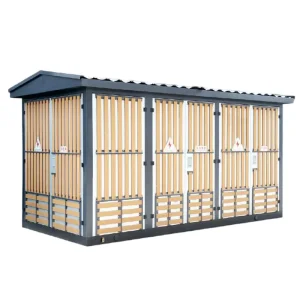
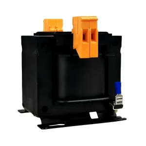
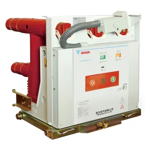
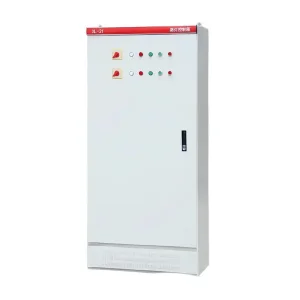
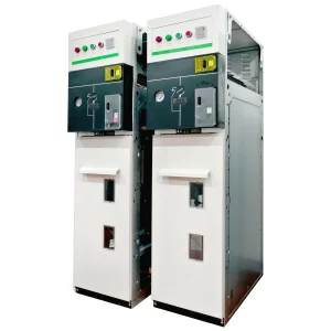
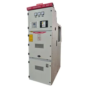
Wholesale XL-21 Power Distribution Cabinet Low Voltage Switchgear Factory, Companies
Frequently Asked Engineering Questions
In-depth technical answers addressing transient overvoltage protection, device selection, and installation best practices.
What is the core technical difference between the 10/350 μs and 8/20 μs test waveforms?
The 10/350 μs waveform represents a direct lightning strike with a fast rise time to peak (10 microseconds) and a prolonged energy discharge tail (decaying to 50% at 350 microseconds). It carries significant charge and specific energy, which requires heavy-duty Class I spark gaps or large MOVs. In contrast, the 8/20 μs waveform simulates indirect, induced electromagnetic surges or internal switching transients. It carries substantially lower total energy, making it the standard test profile for Class II distribution devices.
How do engineers properly size the Maximum Continuous Operating Voltage (Uc)?
Continuous Operating Voltage ($U_c$) must exceed the maximum steady-state system voltage including grid tolerances (typically $+10\%$ to $+15\%$). For a standard 230/400V TN system, an SPD with $U_c \ge 275\text{V}$ is common. In IT or ungrounded systems where an earth fault on one phase raises the neutral-to-ground voltage to line-to-line levels ($\sqrt{3} \times U_0$), an SPD rated for $U_c \ge 385\text{V}$ or $440\text{V}$ is necessary to prevent thermal breakdown from continuous overvoltage.
Why is backup overcurrent protection required upstream of an SPD?
When an internal MOV reaches end-of-life due to repeated transient events or excessive temporary overvoltages, it can degrade into a low-impedance short-circuit path. An upstream dedicated backup fuse or circuit breaker safely isolates the degraded SPD from the main busbar before the main service breaker trips, preventing localized switchboard fires while maintaining primary power availability.
What is the "50 cm Rule" in surge protection installation?
Under IEC 60364-5-53, the total combined lead length (connecting conductor from phase busbar to SPD, plus lead from SPD to the main protective earth terminal) must not exceed 0.5 meters (50 cm). High rate-of-rise transient currents ($di/dt$) create an inductive voltage drop ($\Delta V = L \cdot di/dt$) along the wire of roughly 1 kV per meter. Keeping leads under 50 cm minimizes this added voltage, preserving the device's protective clamping level ($U_p$).
How does a photovoltaic DC surge protector differ from a standard AC SPD?
DC arcs lack a natural zero-crossing point, making them substantially more difficult to extinguish than AC currents. PV-rated SPDs (compliant with IEC 61643-31) use a specialized "Y-configuration" with three varistor paths and integrated high-temperature micro-switches with mechanical arc-barriers. This design reliably extinguishes DC arcs if an MOV fails, preventing sustained fire hazards in 1000V or 1500V DC solar arrays.
What factors cause MOVs to degrade over time, and how can engineers monitor health?
MOVs experience microstructural degradation from recurring low-level switching transients, elevated ambient operating temperatures, and sustained micro-leakage currents. This gradual aging can lead to thermal runaway. Modern predictive maintenance systems monitor varistor health via integrated dry contacts, visual flag indicators, or automated SCADA-connected leakage current sensors that trigger warnings before the unit fails.