Primary Industrial Power & Distribution Assemblies
Explore our core engineered lineup, covering precision machine tool control, automated voltage stabilization, low-frequency uninterruptible power, and robust switchgear enclosures.
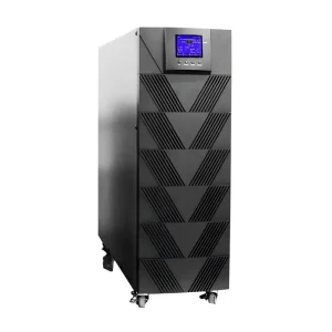
ODM MCL31 Series Low Frequency UPS Technical Supplier, Factories
View Product Specs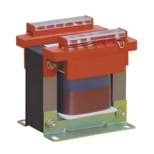
Wholesale BK Series Control Transformers – Reliable Power Solutions Factory, Company
View Product Specs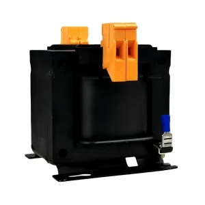
High-Quality JBK5 Series Machine Tool Control Transformer Factories, Companies
View Product Specs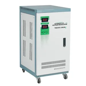
ODM TND/S Two Phase Series Fully Automatic Ac Voltage Regulator Manufacturers, Factory
View Product Specs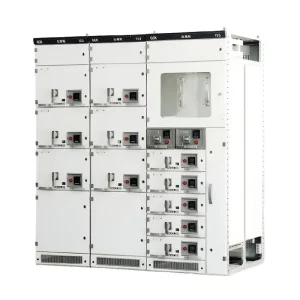
China China GCK Low Voltage Withdrawable Switchgear for Industrial Plants - Reliable Suppliers & Factory Solutions
View Product Specs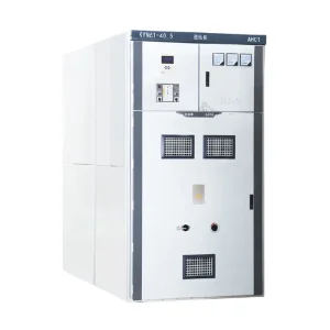
OEM KYN61-40.5 Armoured Moving Type AC Metal Enclosed Switchgear Supplier, Factories
View Product Specs
Wholesale D165T LV Moulded Case Pole Mounted Breaker Digital Trip Unit Manufacturer, Factories
View Product Specs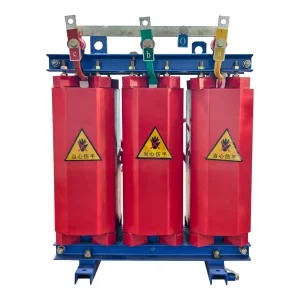
High-Quality SC(B)11 10kv Resin-Insulated Dry Casting Transformer for Electric Supply
View Product SpecsHarmonic Mitigation in High-Density Power Infrastructure
Why modern commercial and industrial power distribution architectures demand custom iron-core series detuned reactors to protect power factor correction capacitor banks and eliminate resonance hazards.
Eliminating Harmonic Resonance
The ubiquity of switch-mode power supplies, variable frequency drives (VFDs), and EV fast chargers creates severe 5th, 7th, 11th, and 13th harmonic current injection. Harmonic filter reactors shift the LC circuit resonant frequency below the lowest dominant harmonic order, preventing catastrophic capacitor detonation.
Thermal & Voltage Stress Damping
By absorbing inter-harmonic transients and limiting fundamental capacitor inrush currents, our series reactors reduce total harmonic distortion (THD-V and THD-I), dramatically extending the operating life of upstream transformer windings, circuit breakers, and sensitive instrumentation.
Global Grid Code Compliance
Regulatory frameworks such as IEEE 519-2022, IEC 61000-3-6, and European EN 50160 impose strict penalties on power pollution. Incorporating tailored detuned reactors ensures that power factor correction (PFC) banks function seamlessly without exceeding allowable grid distortion limits.
Engineering Insight: The Critical Linear Saturation Threshold
A frequent failure mode in lower-grade reactors is core magnetic saturation during minor grid overvoltage events. Our custom ODM reactors maintain a linearity factor ($L/L_N$) exceeding 95% at 1.8 to 2.2 times the rated current ($I_N$), guaranteeing non-saturating suppression even under extreme switching surges and fault transients.
Global Enterprise Sourcing Demands for Harmonic Filter Reactors
Evaluating the mechanical, magnetic, and thermal design criteria required by tier-1 engineering, procurement, and construction (EPC) conglomerates and switchboard manufacturers.
Core Metallurgical Standards & Loss Budgets
International procurement specifications require low-loss, high-permeability cold-rolled grain-oriented (CRGO) magnetic silicon steel sheets (typically M4 or M5 grade, or superior laser-treated grades). Our ODM production process employs precision laser cut multi-gap core configurations interleaved with specialized high-temperature ceramic spacers and micro-gap dampening compounds. This construction eliminates localized fringing flux, prevents eddy-current overheating in the structural clamping plates, and keeps core operating watt losses well below industry averages.
Conductor Topologies: Foil vs. Multi-Strand Wire
Depending on rated ampacity and space envelope constraints, reactors are wound using high-conductivity electrolytic copper (Cu) or electrical-grade aluminum (Al). For low-voltage, high-amperage applications (up to 1200A), our automated foil winding lines produce high fill-factor coils that eliminate inter-layer voltage stress and offer superior short-circuit mechanical strength. For high-frequency tuned filters, multi-strand transposed magnet wire is utilized to mitigate severe skin and proximity effect losses.
Vacuum Pressure Impregnation (VPI) & Environmental Ingress
To operate reliably in harsh, humid, saline, or chemically active industrial environments, standard dip-coating is insufficient. All Mingri ODM reactors undergo a multi-stage Vacuum Pressure Impregnation (VPI) cycle using solventless Class H (180°C) or Class C (200°C) modified epoxy/polyester resins. The computerized polymerization cycle eliminates internal air voids, maximizes dielectric breakdown resistance, prevents moisture ingress, and guarantees whisper-quiet operation below 48–55 dB.
Integrated Thermal Protection & Telemetry
Global procurement agreements require proactive safety telemetry. Every phase limb is fitted with integrated, normally-closed (NC) bimetallic micro-thermostats ($125^\circ\text{C}$ to $150^\circ\text{C}$) or calibrated PT100 / PTC thermistors embedded deep within the winding core hot spots. These sensors link directly to the switchgear's micro-controller, digital trip units, or SCADA infrastructure to trigger protective bank tripping before thermal runaway can occur.
Detuned Filter Reactor Selection & Mathematical Matching
A rigorous breakdown of detuning factors ($p$), series resonant frequency ($f_r$), and standard system architectures for 50 Hz and 60 Hz electrical networks.
| Detuning Factor ($p$) | Resonant Frequency (50 Hz) | Resonant Frequency (60 Hz) | Target Harmonic Orders | Typical Industrial Load Application |
|---|---|---|---|---|
| 5.67% ($X_L/X_C$) | 210 Hz | 252 Hz | 5th, 7th, 11th, 13th | VFD-rich commercial centers, HVAC chillers, cleanrooms with high 5th harmonic content without 3rd order. |
| 7.00% ($X_L/X_C$) | 189 Hz | 227 Hz | Safe anti-resonance (5th & up) | The universal global industrial standard for general factories, water treatment, paper mills, and steel works. |
| 14.00% ($X_L/X_C$) | 134 Hz | 160 Hz | 3rd, 5th, 7th | Single-phase rectifiers, LED infrastructure, arc furnaces, hospitals with heavy single-phase non-linear loads. |
| 0.5% – 1.0% (Tuned) | Exact 250 / 350 Hz | Exact 300 / 420 Hz | Dedicated Absorption | Direct harmonic shunt absorption filtering banks where active reduction of specific harmonic orders is mandatory. |
Calculated Voltage Rise Compensation
Connecting a series detuned reactor causes a terminal voltage boost across the power capacitor bank according to $U_C = U_N / (1 - p)$. For example, in a 400V grid with a 7% reactor, the capacitor sees approximately 430V. Our ODM engineering team provides matched reactor-capacitor package ratings (e.g., 480V or 525V rated capacitors) to prevent dielectric punch-through.
Acoustic Resonance Attenuation
Harmonic currents cause magnetostrictive deformation in the iron core at frequencies of 250 Hz, 350 Hz, and higher. Our proprietary core potting and elastomeric shock-cushioning dampers drop operational acoustic emissions down to ultra-quiet levels, enabling seamless deployment in commercial, indoor hospital, and office building switchrooms.
Short-Circuit Dynamic Stability
Under momentary short-circuit conditions, inductive windings experience violent Lorentz forces. Our automated winding machines incorporate reinforced fiberglass edge ties, high-tensile banding, and high-modulus resin blocks, providing guaranteed dynamic short-circuit withstand up to 25 times nominal current for 2 seconds.
Macro-Industry Deployments & Operational Case Studies
From gigawatt-scale renewable generation sites to hyperscale data centers, explore how customized harmonic filter reactors protect capital assets worldwide.
Renewable Energy: Solar PV & BESS
Utility-scale central inverters and Battery Energy Storage Systems (BESS) switch high-frequency PWM IGBTs, creating high-frequency ripple currents. We manufacture customized medium-voltage iron-core and air-core filter reactors that isolate inverter steps, stabilize interconnect points, and eliminate transformer overheating at the substation collector bus.
Hyperscale AI & Cloud Data Centers
Modern data centers run non-linear server PSUs alongside vast arrays of inverter-driven CRAC units. The resulting low power factor and high harmonic profiles threaten zero-downtime SLAs. Our compact, high-power-density 7% and 14% detuned reactors integrate directly into space-constrained LV power modules and busways with minimal thermal footfall.
Heavy Metallurgical & Chemical Plants
Continuous-casting steel mills, electric arc furnaces (EAF), and electrolysis facilities inject fluctuating, unbalanced reactive currents accompanied by severe 2nd, 3rd, and 5th harmonics. We engineer ruggedized, forced-air or water-cooled reactor variants capable of withstanding cyclic thermal shocks and corrosive industrial atmospheres.
Advanced Manufacturing Processes & Quality Architecture
Inside our specialized Yueqing production facilities: precision robotic winding, high-pressure VPI processing, and fully automated digital test benches.
Automated Multi-Layer Foil & Wire Winding
Our workshop is outfitted with CNC foil winding systems featuring pneumatic constant-tension regulation and automatic edge-alignment sensors. By utilizing copper or aluminum foil with double-sided Nomex aramid paper inter-turn insulation, our coils achieve virtually void-free winding structures. This structure minimizes internal thermal gradients and delivers exceptional heat dissipation capabilities even under continuous harmonic overcurrent.
Precision Laser-Gapped Core Stacking
The air gap in an iron-core reactor is the heart of its magnetic linearity. Rather than relying on a single large gap—which creates excessive fringe flux and severe local heating—our engineering team divides the gap into multiple micro-gaps isolated with non-magnetic, high-temperature composite spacers. Each core limb is pressed under calibrated hydraulic clamps and bound with high-strength non-metallic tensioning bands.
Dual-Cycle Vacuum Pressure Impregnation (VPI)
Coil assemblies are pre-heated in computerized ovens, transferred into a hermetically sealed vacuum chamber to extract all trapped air and moisture at < 20 Pa, and subsequently backfilled with high-grade electrical insulating resin under high pneumatic pressure. This deep resin penetration solidifies the entire winding-core assembly into a single, monolithic, moisture-proof block with extraordinary mechanical rigidity.
100% Routine Factory Acceptance Testing (FAT)
Every single reactor manufactured on our ODM line undergoes strict automated testing prior to dispatch: inductance measurement across all three phases, winding resistance balance check, power loss dissipation verification at fundamental and rated harmonic frequencies, inter-turn overvoltage testing, and high-voltage dielectric withstand verification (up to 5 kV AC for LV; up to 95 kV BIL for MV).
Technology Roadmap & Next-Gen Power Quality (2025–2035)
Anticipating the technological shifts in high-frequency power electronics, active-passive hybridization, and IoT-enabled predictive asset management.
Nanocrystalline & Amorphous Alloy Cores
As Wide Bandgap (WBG) semiconductors like Silicon Carbide (SiC) and Gallium Nitride (GaN) enter industrial converters, switching frequencies are rising from 2–5 kHz up to 20–100 kHz. We are actively engineering ultra-low-loss nanocrystalline and amorphous magnetic core reactors to deliver extreme attenuation at frequencies where conventional silicon steel exhibits excessive core loss.
Active-Passive Hybrid Topologies
The future of power quality is not pure passive or pure active, but an optimized hybrid. Large capacitive reactive power is cost-effectively supplied by detuned reactor-capacitor banks, while residual high-order inter-harmonics are dynamically canceled by small-footprint Active Power Filters (APFs). Our ODM reactors are pre-tuned for seamless integration alongside digital active conditioners.
Embedded Fiber-Optic Thermal Sensing
Moving beyond basic bimetallic switches, our smart reactors can be built with embedded distributed fiber-optic temperature sensors (DTS) or wireless RFID/NFC temperature patches inside the internal winding hot spots. This enables real-time thermal modeling, cloud-based health forecasting, and condition-based predictive maintenance via switchgear SCADA.
International Regulatory Compliance & Engineering Assurance
Seamlessly integrating into global supply chains with multi-standard testing, tropicalized insulation, and dedicated engineering consultation.
IEC, IEEE, and UL Harmonization
Our harmonic filter reactors are engineered and tested in strict accordance with IEC 60076-6 (Power reactors), IEC 61000-4-7 (Harmonic measurement techniques), IEEE Std C57.21, and IEEE Std 519-2022. Comprehensive type test certificates from independent CNAS/ILAC-accredited high-voltage test laboratories verify temperature rise limits, impulse withstand voltage, and linear impedance consistency across varying current loads.
Tropicalization & Severe Environment Packaging
For installations in tropical coastal regions, desert mining fields, or sub-zero arctic substations, our reactors are coated with anti-fungal, moisture-resistant, and salt-mist protective finishes conforming to Class C4 and C5 atmospheric corrosivity requirements. Marine-grade copper busbars with specialized tin- or silver-plating prevent galvanic corrosion at terminal connection interfaces.
OEM Private Labeling & Custom Mechanical Form Factors
We provide full white-label and ODM customization for global switchboard builders and panel integrators. This includes tailor-made busbar geometries, vertical or horizontal mounting arrangements to fit standard European (e.g., Prisma, Sivacon) and American switchgear cubicles, customized terminal blocks, and custom branding labels with your company's model nomenclature.
Turnkey Engineering Support & Single-Line Analysis
Selecting the right reactor requires deep electrical network analysis. Our application engineering team offers complimentary review of customer single-line diagrams (SLD), harmonic background surveys, and capacitor bank ratings to calculate precise detuning factors, preventing parallel resonance and eliminating nuisance circuit breaker trips prior to hardware fabrication.
Frequently Asked Questions for Electrical Engineers & Buyers
In-depth technical answers addressing detuning calculations, core saturation concerns, thermal limits, and global sourcing parameters.
A detuned reactor is engineered to prevent parallel resonance between the power factor correction (PFC) capacitor bank and upstream transformer inductance. Its series resonant frequency ($f_r$) is deliberately placed below the lowest dominant harmonic frequency (typically 189 Hz for a 7% reactor in a 50 Hz system, positioned below the 250 Hz 5th harmonic). It behaves inductively for all harmonic frequencies, protecting capacitors from overloading. Conversely, a tuned filter reactor is matched to create an exact zero-impedance series resonant path at a specific harmonic frequency (e.g., exactly 250 Hz for the 5th harmonic), intentionally trapping and draining that specific harmonic current out of the system.
When an inductor is placed in series with a capacitor in an AC system, it creates a voltage rise across the capacitor terminals according to the equation $U_C = U_N / (1 - p)$. For instance, in a 400V grid ($U_N$) with a 7% detuned reactor ($p = 0.07$), the actual operational fundamental voltage on the capacitor terminals increases to approximately $400 / 0.93 = 430.1\text{ V}$. When combined with harmonic overvoltages, standard 400V-rated capacitors would suffer rapid dielectric breakdown. Therefore, higher-voltage capacitors (rated at 480V, 525V, or 690V) must be specified to ensure long-term operational reliability.
Linearity denotes the current multiple at which the reactor's core begins to saturate and lose its design inductance ($L$). Under steady-state conditions, fundamental and harmonic currents sum up to an RMS value higher than nominal ($I_{rms} > I_1$). During grid voltage spikes or capacitor energization, current surges can reach 1.8 to 2 times rated current ($I_N$). If the core saturates, the inductance drops sharply, shifting the resonant frequency upwards right into the harmonic zone (e.g., 250 Hz), triggering sudden resonance, circuit breaker tripping, and capacitor destruction. Our reactors are engineered with high-permeability grain-oriented steel with multi-gap cores to maintain $L \ge 95\%$ of nominal inductance at $1.8 \times I_N$ (and up to $2.2 \times I_N$ on custom requests).
A 7% reactor sets the resonant frequency at 189 Hz (in 50 Hz grids) or 227 Hz (in 60 Hz grids), which protects against 5th harmonic (250/300 Hz) resonance and above. However, if a facility possesses a significant amount of single-phase rectifiers, LED drivers, commercial IT equipment, or electric welding units, it generates severe 3rd harmonic currents (150 Hz or 180 Hz). A 7% reactor would cause near-resonant amplification of this 3rd harmonic. In such environments, a 14% detuned reactor must be deployed. It shifts the resonant frequency down to 134 Hz (50 Hz grid) or 160 Hz (60 Hz grid)—well below the 3rd harmonic—ensuring complete network safety.
Under rated harmonic excitation, iron-core reactors naturally emit acoustic hum due to alternating magnetic flux forces across the air gaps and core laminations. Mingri addresses this through three advanced manufacturing techniques: First, we segment the air gap into numerous small micro-gaps isolated with high-density ceramic shims. Second, core laminations are bonded using vacuum pressure impregnated resins with high mechanical modulus. Third, the entire base structure sits on vibration-absorbing isolation blocks. As a result, our standard units operate below 48 to 55 dBA, satisfying strict indoor building codes.
Because harmonic currents induce significant high-frequency eddy-current heating, our coils are built with thermal safety margins utilizing Class H (180°C) or Class C (200°C) insulation systems. Furthermore, every three-phase limb is fitted with calibrated, hermetically sealed bimetallic micro-switches (NC contacts, typically activating at 125°C or 140°C) embedded directly into the central coil hot spot. We also supply custom units equipped with PT100 resistance temperature detectors (RTDs) or PTC thermistors for continuous digital telemetry to switchgear automation controllers.
Yes. As an specialized ODM manufacturer, we frequently tailor core dimensions, terminal lug geometries, and busbar orientation (top entry, front entry, or side stabs) to fit tight physical footprints in retrofit switchgear cubicles. We provide comprehensive 3D STEP models, dimensional drawings, and thermal dissipation footprints to your mechanical design team within 48 hours of specification review.
Every shipment includes an individualized Factory Acceptance Test (FAT) report detailing routine test results (inductance per phase, resistance balance, dielectric withstand at 3.5kV–5kV, core loss, and hot-spot temperature rise validation). Additionally, we provide Certificate of Origin, mill test certificates for silicon steel and copper conductors, type test reports from accredited high-voltage testing authorities, and standard ISO 9001/14001 compliance documentation.
Protection Devices, Reactors & Packaged Substations
Complete your power distribution topology with our high-performance circuit breakers, series reactors, lighting transformers, and integrated American-style package substations.
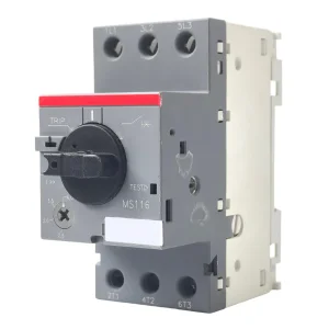
ODM MS116 Low Voltage Motor Protection Circuit Breaker Supplier, Companies
View Product Specs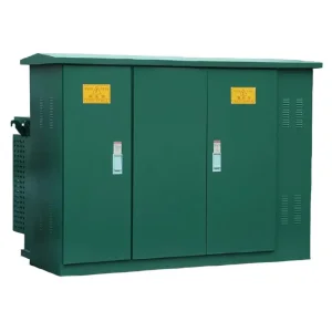
China China ZGS11-12 Combined American Prefabricated Substation - Efficient Power Solution
View Product Specs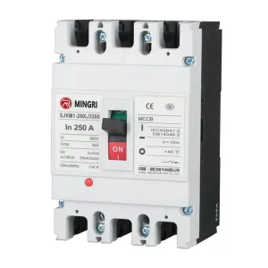
Wholesale SJKM1 Moulded Case Circuit Breaker (MCCB) from China Suppliers
View Product Specs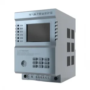
Wholesale Single phase current limiting protector 20-80A 220VAC Manufacturer, Company
View Product Specs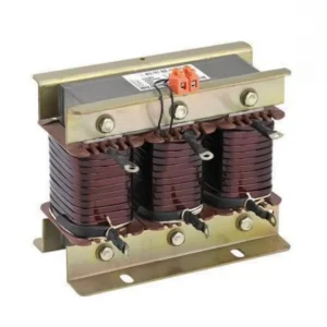
High-Quality CKSG Series Low Voltage Series Reactor Manufacturers, Manufacturer
View Product Specs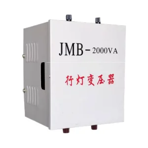
ODM JMB/BJZ/DG/BZ(DM) Series Lighting & Hand Lamp Control Transformer Suppliers
View Product Specs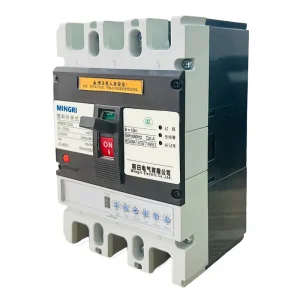
Wholesale SJKM3E Electronic Circuit Breaker (ECB) with Smart Protection Suppliers
View Product Specs