Primary Frequency Conversion & Power Control Systems
Our intelligent variable frequency drive (VFD) lineup couples advanced Vector Sensorless Control (SVC) algorithms with robust power stage engineering. Designed to regulate AC asynchronous induction and permanent magnet synchronous motors (PMSM), these systems optimize torque curves, eliminate inrush starting currents, and slash plant energy consumption.
-
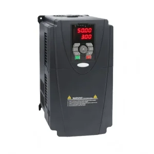 ODM MC9001 Series High Performance Frequency Converter Supplier, ManufacturerView Technical Specifications
-
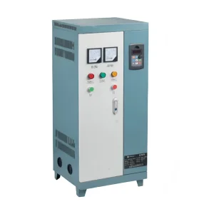 ODM MC3000 Series Variable Frequency Cabinet With Power Manufacturers, CompanyView Technical Specifications
-
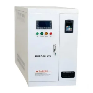 OEM MCBP Series Variable Frequency Power Supply Manufacturer, FactoryView Technical Specifications
-
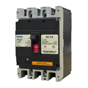 High-Quality SJKM3 MCCB Moulded Case Circuit Breaker with Overload Protection Supplier, CompanyView Technical Specifications
-
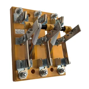 Wholesale HS13BX Double Throw Rotary Type Knife Disconnect Switch Manufacturer, FactoryView Technical Specifications
-
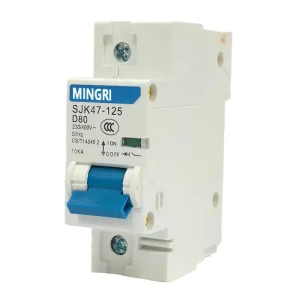 High-Quality SJK47-125 MCB Miniature Circuit Breaker - Reliable 230V/400V Protection from China Suppliers and FactoryView Technical Specifications
-
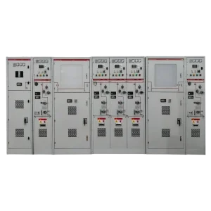 Wholesale SafeRing-12 Fully insulated inflatable ring switchgear with Insulation Protection Manufacturers, CompaniesView Technical Specifications
-
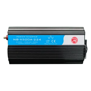 High-Quality 500W DC to AC Power Inverter X500 with EU Socket - China Suppliers & Factory for Efficient Power ConversionView Technical Specifications
Advanced VFD Topologies: From Solid-State Inverters to Active Front Ends
Variable Frequency Drives (also known as Variable Speed Drives, AC Inverters, or Frequency Converters) serve as the cornerstone of contemporary electrical power conversion. By transforming fixed-voltage, fixed-frequency utility AC power into infinitely adjustable frequency and voltage outputs, modern drives govern motor dynamics with surgical precision while minimizing electrical stress.
Rectification & DC-Link Stabilization
The initial stage converts balanced three-phase AC mains to intermediate DC via diode bridges or controlled Silicon-Controlled Rectifiers (SCRs). Our industrial units utilize metalized film or high-temperature electrolytic capacitor banks with integrated swinging chokes, mitigating ripple voltages, buffering instantaneous load step transients, and suppressing line-side current spikes.
SVPWM Inverter Stage
Utilizing insulated-gate bipolar transistors (IGBTs) or Silicon Carbide (SiC) switches, the inverter synthesizes variable-frequency three-phase AC through Space Vector Pulse Width Modulation (SVPWM). SVPWM optimizes DC-bus utilization by up to 15.5% compared to sinusoidal PWM, drastically reducing switching harmonic losses and acoustic motor noise.
Field-Oriented Vector Control (FOC)
Decoupling magnetic flux and torque vectors via Park and Clark transformations, our MC9001 and MC3000 series achieve instantaneous torque response (<5ms). This closed-loop or sensorless vector control delivers up to 200% rated starting torque at near-zero shaft speeds, critical for hoists, extruders, and positive displacement pumps.
| Drive Topology / Parameter | Standard 6-Pulse Inverter | 12 / 18-Pulse Rectifier | Active Front End (AFE) Inverter |
|---|---|---|---|
| Line-Side Harmonic Distortion (THDi) | 35% – 45% (Unmitigated) | 8% – 12% (Phase Shifted) | < 3% – 5% (IEEE 519 Compliant) |
| Four-Quadrant Energy Regeneration | Requires Dynamic Braking Resistors | No (Dissipative Only) | Full Bi-Directional Grid Feedback |
| Input Displacement Power Factor (cos φ) | 0.92 – 0.95 at Full Load | 0.96 – 0.98 | Near Unity (1.00) Controllable |
| DC-Bus Voltage Boost Capability | No (Direct Rectified Peak) | No (Transformer Fixed) | Yes (Active Boost during Line Sag) |
| Typical Industrial Applications | Standard HVAC, Blowers, Light Conveyors | Medium Heavy Industry, Pumps >250kW | Cranes, Dyno Benches, Mining Hoists |
Technology Roadmap: Wide-Bandgap Silicon & Edge-AI Integration
The future of variable frequency drive engineering centers on three converging vectors: semiconductor physics revolution, distributed Edge intelligence, and common-DC-bus microgrid energy recovery. Here is how Mingri Electric and industrial pioneers are shaping the next decade of motion conversion.
SiC & GaN Semiconductor Platforms
Migrating from traditional Silicon IGBTs to Silicon Carbide (SiC) MOSFETs allows carrier frequencies to scale above 32 kHz without thermal penalty. This eliminates audible motor hum, cuts switching losses by up to 68%, and drastically shrinks physical heatsink footprints—yielding power density improvements exceeding 40%.
Embedded Neural Predictive Maintenance
Modern MC9001 microcontrollers embed high-speed Fast Fourier Transform (FFT) algorithms directly into the drive core. By analyzing ripple signatures in motor phase currents, the drive detects bearing raceway pitting, rotor bar eccentricity, and stator insulation leakage weeks before catastrophic field failure occurs.
Zero-Trust Cyber-Physical Fieldbuses
With the rapid proliferation of industrial IoT, our drive cabinets embed native hardware cryptography, TLS 1.3 secured OPC UA over Time-Sensitive Networking (TSN), Profinet IRT, and EtherCAT. This ensures millisecond-level synchronous deterministic multi-axis motion while guarding OT infrastructure against malicious cyber incursions.
Engineered Application Solutions Across Critical Global Sectors
Variable speed motor control is not a one-size-fits-all commodity. Different operating profiles impose unique electromagnetic, thermal, and mechanical stresses. Mingri Electric’s custom drive enclosures and motor controllers solve specialized application pain points worldwide.
Heavy Industry: Mining, Metallurgy & Material Handling
Crushers, ball mills, and continuous downhill overland conveyors demand ruggedized components. Our heavy-duty drive cabinets provide continuous 150% overload capacity for 60 seconds and 180% for 2 seconds. In downhill conveyor applications, regenerative Active Front Ends return millions of kilowatt-hours directly back to the substation grid rather than burning energy off as waste heat across massive resistor banks.
- Zero-speed full torque hold for hoist mechanical brake sequencing
- Conformal PCB coating complying with Class 3C3/3S3 aggressive chemical gas environments
- Integrated SJKM3 MCCB feeder protection preventing short-circuit fault propagation
Municipal Water Treatment, Desalination & Pumping
Centrifugal pumps adhere to the affinity laws, where power demand is proportional to the cube of rotational speed. A modest 20% reduction in motor speed yields up to a 50% drop in energy consumption. Our MC3000 drive cabinets integrate multi-pump cascade controllers, anti-cavitation logic, and smooth pipe-fill algorithms that eliminate destructive hydraulic water hammer events.
- Automated de-ragging and reverse pump purging cycles to dislodge impellers
- Dedicated sleep/wake modes tailored to fluctuating municipal reservoir pressure levels
- Galvanically isolated transducer inputs for 4-20mA pressure/flow sensor loops
HVAC, Cleanrooms & Mission-Critical Data Centers
Hyperscale cooling plants require non-disruptive, ultra-quiet operations. Mingri VFD architectures feature variable switching frequencies up to 16 kHz to eliminate audible motor whine. Native BACnet MS/TP and Modbus RTU protocols interface directly with Building Management Systems (BMS), maintaining chiller and AHU setpoints to within ±0.1°C precision.
- Fireman's Override Mode (smoke purge override) forcing drives to run to destruction during fires
- Resonance skip frequency bands (up to 3 distinct zones) to protect ducting from mechanical fatigue
- Ultra-low EMI emissions compliant with IEC 61800-3 Category C1 for sensitive IT infrastructure
Renewable Energy Balance-of-Plant & Photovoltaic Systems
Coupling high-efficiency motor drives directly with solar arrays requires intelligent Maximum Power Point Tracking (MPPT) firmware. In off-grid agricultural solar pumping and utility-scale balance-of-plant systems, our variable frequency converters dynamically balance PV DC-bus volatility against motor load torque curves, preventing motor stalling during intermittent cloud cover.
- Seamless hybrid switching between solar PV array inputs and grid/diesel generator inputs
- Integrated SJKS1-B Series 80kA Class B surge arresters for utility-grade lightning protection
- Dry-run sensorless detection protecting submersible borehole pumps from running without fluid
China Industry 4.0: The Yueqing Manufacturing & Supply Chain Advantage
Headquartered in Yueqing, Zhejiang Province—the globally recognized epicenter of low- and medium-voltage electrical apparatus—Mingri Electric leverages unparalleled regional cluster advantages, comprehensive vertical integration, and fully automated production lines.
Vertical Supply Chain Compression
Within a 15-kilometer radius of our Yueqing smart facility, 95% of our bill-of-materials components are designed, stamped, molded, or drawn. From precision sheet-metal cabinet fabrication (KYN61, SafeRing enclosures) to custom copper busbars and silicone-impregnated pulse transformers, this localization compresses component lead times from months to hours.
Automated SMT & Dual Burn-in Testing
All drive control boards and power interface cards are populated on high-speed Japanese surface-mount technology (SMT) lines with 3D Automated Optical Inspection (AOI). Every completed variable frequency converter undergoes 72 hours of continuous thermal cyclic burn-in testing under full rated inductive motor load at 50°C ambient temperatures before shipping.
Agile OEM & Custom Firmware Tooling
Global system integrators demand tailored software hooks. Our on-site R&D engineering team provides rapid turnaround for bespoke firmware routines—including customized PID control tables, custom Modbus register mappings, automated braking chopper logic, and personalized white-label branding on hardware nameplates and user manuals.
EPC Technical Sizing & Derating Selection Methodology
Specifying a variable frequency drive requires evaluating real-world environmental factors and installation topology beyond standard motor horsepower ratings. Operating a drive outside its thermal or mechanical envelope causes premature capacitor breakdown and nuisance overcurrent trips.
1. Altitude Derating (> 1000m)
At high altitudes, thinner air decreases convective cooling capacity and reduces the dielectric insulation strength of air gaps. For installations above 1,000 meters (3,300 feet), derate the continuous output current by 1% per additional 100 meters, with a standard operating ceiling of 4,000 meters.
2. Ambient Temperature (> 40°C)
Mingri VFDs operate at 100% continuous rated current up to 40°C. For enclosures exposed to high ambient temperatures up to 50°C, apply a derating factor of 1.5% to 2.0% per 1°C elevation above 40°C, or implement forced air conditioning within the switchgear lineup.
3. Cable Length & dv/dt Mitigation
Steep voltage rise times (high dv/dt exceeding 5 kV/µs) through long motor feed cables induce reflected wave phenomena, doubling peak terminal voltages up to 1,600V at the motor stator. For cable lengths exceeding 50 meters, specify output line reactors; for runs >100 meters, integrate LC Sinewave Filters.
| Carrier Frequency (kHz) | Current Derating Factor | Acoustic Motor Noise | Motor Insulation Stress (dv/dt) | Drive Thermal Dissipation |
|---|---|---|---|---|
| 2.0 kHz (Heavy Torque) | 100% (No Derate) | Audible Induction Hum | Lowest (Gentle Wavefront) | Minimal Inverter Losses |
| 4.0 kHz (Standard Factory) | 100% (Standard Rating) | Moderate | Nominal Standard | Balanced Efficiency |
| 8.0 kHz (HVAC / Commercial) | 85% – 90% Derate | Very Low | Elevated (Reactor Advised) | Moderate Heat Rise (+12%) |
| 12.0 – 16.0 kHz (Acoustic Silence) | 70% – 75% Derate | Near Silent (Inaudible) | High (Requires dv/dt Filter) | Maximum Heatsink Load (+28%) |
International Compliance, Functional Safety & Grid Codes
Global industrial facilities demand unyielding safety, electromagnetic compatibility, and rigorous quality systems. Mingri Electric power electronics are tested and certified under worldwide engineering directives.
IEC / EN 61800-5-1
Comprehensive electrical, thermal, and functional safety compliance. Ensures high clearance and creepage distances, shock hazard protection, and catastrophic arc containment.
IEC / EN 61800-3 (EMC)
Electromagnetic compatibility validation covering both conducted and radiated emissions. Units integrate Category C2 or C3 RFI/EMI filters for clean grid interfacing.
Safe Torque Off (STO)
Dual-channel hardware-level Safe Torque Off certified to SIL 3 (IEC 61508) and PLe (ISO 13849-1), removing output drive power without needing upstream main contactor drops.
ISO Quality Triad
Certified manufacturing management adhering strictly to ISO 9001:2015 (Quality), ISO 14001:2015 (Environmental stewardship), and ISO 45001:2018 (Occupational Health & Safety).
Integrated Switchgear, Protection Breakers & Incomer Apparatus
A truly resilient motor drive center requires more than just high-grade inverters. It demands coordinate upstream protection, rapid isolation, surge suppression, and active safety interlocks. Mingri Electric supplies the full electrical distribution spectrum.
-
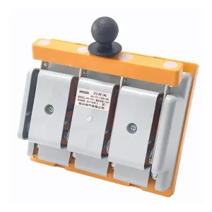 OEM HD11F Single Throw Anti-Error Knife Switch Suppliers, FactoryView Technical Specifications
-
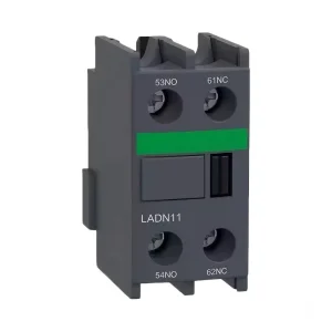 ODM LADN 1NO 1NC Auxiliary Contact For AC Contactor Manufacturers, ManufacturerView Technical Specifications
-
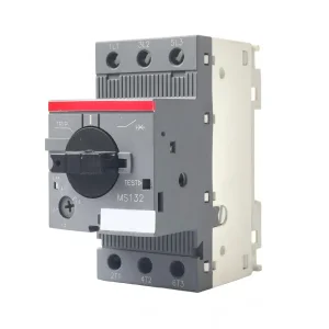 OEM China MS132 Low Voltage Motor Protection Circuit Breaker - 25A, 15kW, 100kA, Factory SuppliersView Technical Specifications
-
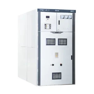 ODM KYN61-40.5 Armoured Moving Type AC Metal Enclosed Switchgear - High-Voltage SolutionView Technical Specifications
-
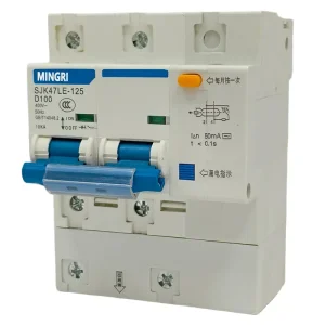 OEM SJK47LE-125 Residual Current Circuit Breaker (RCCB) Manufacturers, CompaniesView Technical Specifications
-
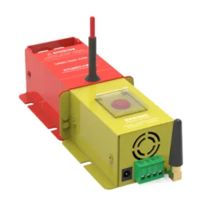 OEM Intelligent wireless automatic gas fire extinguishing device-Hot Aerosol Series Manufacturer, FactoryView Technical Specifications
-
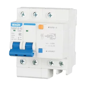 OEM SJK47LE-63 RCCB: Reliable Earth Leakage Protection for 230V/400V AC Systems SupplierView Technical Specifications
-
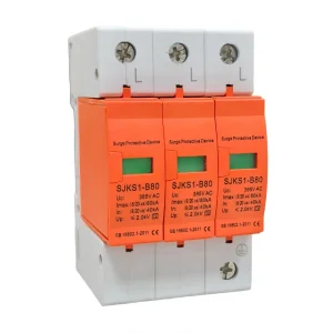 High-Quality SJKS1-B Series Surge Protection Device 80KV 385V Factories, CompaniesView Technical Specifications
Frequently Asked Questions on Variable Frequency Drives
Detailed technical answers addressing inverter topology selection, motor bearing protection, harmonic mitigation standards, and installation best practices.
Scalar (V/f) control maintains a fixed mathematical ratio between output voltage and output frequency. It is ideal for multi-motor ganged setups and low-dynamic loads like simple fans and centrifugal pumps. Sensorless Vector Control (SVC) mathematically decouples magnetizing current from torque-producing current through real-time motor modeling. This gives dynamic torque response (<10ms), eliminates slip speed errors, and delivers 150%–200% rated holding torque at near-zero frequencies without requiring costly rotary encoder feedback.
Fast IGBT switching produces high common-mode voltages (CMV) and capacitive coupling between the motor stator windings and rotor. This builds up shaft voltage. When this potential exceeds the dielectric strength of the bearing grease film, an Electrical Discharge Machining (EDM) spark jumps across the bearing balls, causing microscopic pitting, fluting grooves, and premature bearing destruction. Prevention strategies include installing conductive shaft grounding rings, utilizing ceramic/insulated motor non-drive end bearings, and inserting common-mode chokes at the VFD output terminals.
Standard diode rectifiers draw non-sinusoidal, discontinuous current pulses, producing high Total Harmonic Distortion (THDi of 35%–45%) that pollutes the substation transformer and trips sensitive equipment. An Active Front End replaces passive diodes with an IGBT-controlled bridge and an LCL filter. By switching at high frequencies, the AFE synthesizes pure sinusoidal input currents in phase with grid voltage, dropping THDi below 3%–5% across all load points and achieving near-unity power factor (cos φ = 0.99).
Dynamic braking uses a chopper transistor to dump regenerative kinetic energy into heavy ceramic resistors as waste heat. It is cost-effective for intermittent, low-duty braking cycles (e.g., occasional machine emergency stops or decelerating a centrifuge once every two hours). For continuous overhauling loads—such as downhill conveyor systems, deep mine hoists, continuous coil unwinders, or multi-axis dynamic engine dynamometers—an AFE regenerative unit is economically superior because it converts kinetic energy back into clean AC electricity returned directly to the plant bus, paying for itself within months.
To ensure precise sizing, provide: (1) Motor nameplate data (kW/HP, rated full-load amps, voltage, rated frequency, efficiency class, and motor type: Induction, PMSM, or SynRM); (2) Load torque profile (Variable torque vs. Constant torque, required starting torque, overload duration); (3) Feed line parameters (Supply voltage, fault level/short-circuit current Icu, transformer rating); (4) Operating environment (Altitude, ambient max/min temperature, humidity, dust class); and (5) Control topology (Fieldbus protocols, analog I/O counts, bypass requirements, Safe Torque Off rating).
IEC 61800-3 governs electromagnetic emissions from adjustable speed electrical drives. Category C1 covers equipment rated <1,000V intended for unrestricted use in the first environment (domestic/residential buildings). Category C2 covers stationary equipment installed in residential areas only by a qualified technician. Category C3 applies strictly to the second environment (industrial premises with independent transformers). Selecting the correct embedded EMC filter prevents high-frequency conducted interference from disrupting computers, PLCs, and telecommunication infrastructure.