High-Efficiency Medium & Low Voltage Apparatus
Explore our certified low-loss electrical switchgear, transformers, and industrial control systems optimized for thermal dissipation control, minimal no-load core losses, and high operational reliability.
The Global Imperative for Low-Loss Power Infrastructure
In electrical transmission and distribution systems, technical losses account for 6% to 9% of total global electricity generation. Leading OEM low-loss manufacturers are driving structural efficiency shifts across international power architectures.
Grid Transformation & Decarbonization Mandates
Global utility frameworks, such as the European Union’s Ecodesign Directive (Tier 2), the United States DOE 2027 Energy Conservation Standards, and China’s State Grid Level-1 Energy Efficiency requirements, have made high-loss legacy infrastructure obsolete. Modern procurement frameworks penalize no-load (iron) and load (copper) losses via Total Owning Cost (TOC) capitalization formulas ($/watt).
Hyperscale AI & Cloud Infrastructure Loads
The exponential growth of accelerated computing clusters and hyperscale cloud campuses requires continuous mega-wattage feeds with Power Usage Effectiveness (PUE) targets below 1.15. Low-loss switchgear assemblies, compact vacuum breakers, and low-impedance busway interfaces prevent critical voltage sags, localized overheating, and unnecessary cooling parasitic loads within mission-critical facilities.
OEM/ODM Ecosystem Re-engineering
Tier-1 equipment engineering has migrated from localized workshops to automated fabrication centers utilizing robotic core stacking, vacuum pressure impregnation (VPI), laser-guided busbar welding, and helium mass spectrometry leak detection. OEMs like Mingri Electric integrate rigorous material validation to ensure high magnetic permeability and minimal thermal degradation over 30+ year lifecycle horizons.
Physics and Metallurgy of Low-Loss Electrical Systems
Achieving true low-loss performance in electrical apparatus requires eliminating dissipative thermal mechanisms across electromagnetic circuits, conduction interfaces, and dielectric mediums.
1. Hysteresis & Eddy Current Mitigation
Transformer magnetic cores deploy cold-rolled grain-oriented (CRGO) electrical steel or amorphous ribbons (20–25 µm thickness). Laser scribing refines magnetic domain widths, constraining hysteresis loop areas. 45-degree mitered step-lap joint architecture drastically minimizes magnetic reluctance at core corners, driving no-load excitation losses down by up to 35% compared to traditional butt-lap joints.
2. Conductor Joule Heat ($I^2R$) Suppression
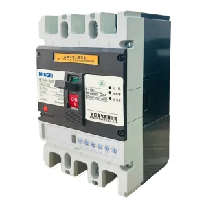
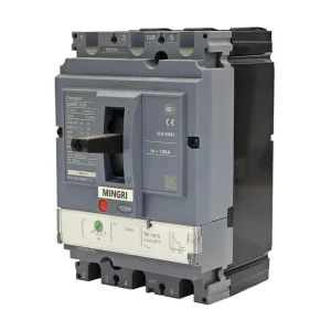
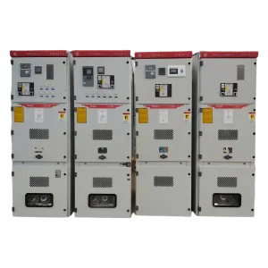
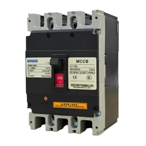
In medium-voltage switchgear (e.g., KYN28, RM6) and low-voltage molded case breakers (SJKM series), load losses scale with contact and conductor resistance. Utilizing oxygen-free T2 copper (electrical conductivity ≥ 100% IACS) with silver electroplating (8–12 µm) across primary contacts stabilizes micro-ohmic junction resistances below critical degradation thresholds under continuous full-load ampacity.
3. Dielectric Loss Dissipation (tan δ)
High-voltage solid-insulation systems and gas-insulated ring main units (GIS) undergo extreme electrical stress fields. Premium epoxy cast resins with silica micro-fillers yield an ultra-low dielectric dissipation factor (tan δ < 0.004). This suppresses continuous capacitance charging losses while preventing internal partial discharges (PD levels verified < 5 pC at 1.2 Un).
4. Vacuum Interruption Contact Dynamics
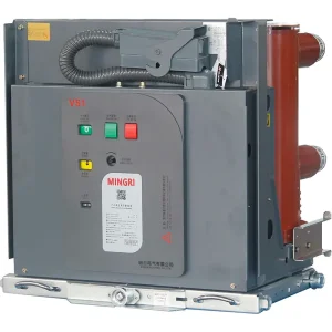
In vacuum circuit breakers (VS1 series), current interruption occurs in a hermetically sealed vacuum chamber (< 10^-5 Pa). Cup-type transverse or axial magnetic field (AMF/TMF) contact geometries force the high-current electric arc to remain diffuse, avoiding localized anode spot formation, reducing contact burn-off, and preserving pristine micro-contact topologies over thousands of mechanical operations.
| Apparatus Category | Legacy Baseline Metric | OEM Low-Loss Target Metric | Material / Design Innovation | Annual Efficiency Impact |
|---|---|---|---|---|
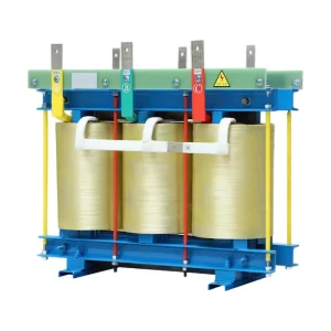
| 10kV Dry-Type Transformers (SG(B)10 / SCB13) | No-load loss: 2,450 W (1,000 kVA) | No-load loss: 1,580 W (1,000 kVA) | High-permeability HiB CRGO sheets, step-lap joints, Nomex Class H insulation | ~7,620 kWh Saved / Year |
| Oil-Immersed Transformers (S11-M Series) | Load loss: 10.3 kW (1,250 kVA) | Load loss: 8.8 kW (1,250 kVA) | Continuous transposed copper conductors (CTC), multi-channel winding cooling | ~13,140 kWh Saved / Year |
| MV Air / Gas Switchgear (RM6 / KYN28-12) | Circuit resistance: > 90 µΩ / pole | Circuit resistance: < 45 µΩ / pole | Multi-lam contact fingers, 99.99% E-Cu buswork, automated torque monitoring | 390 W continuous thermal offset |
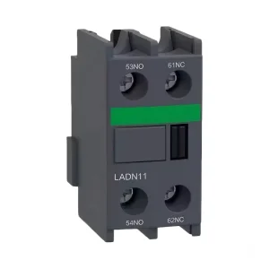
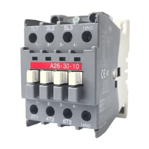
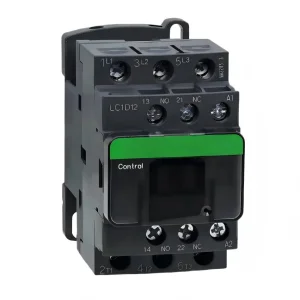
| Industrial Contactors (A9–300, LC1D) | Coil hold power: 22–35 VA | Coil hold power: 3.5–6 VA | Dual-frequency electronically controlled coils, low-remanence soft magnetic armatures | 82% reduction in continuous control loss |
Mission-Critical Application Scenarios & Case Engineering
Low-loss switchgear and transformers are engineered to deliver distinct, quantifiable financial and operational advantages across extreme industrial conditions.
1. Utility-Scale Solar PV & Storage Step-Up
Photovoltaic generation operates at fluctuating daytime capacity factors and high night-time idle conditions. Installing OEM low-loss step-up transformer packages (ZGS11 or SG(B)10 series) ensures night-time tare core losses are cut by over 30%, conserving battery reserves and maximizing net grid exported kilowatt-hours over 25-year Power Purchase Agreements (PPAs).
2. AI Data Centers & Hyperscale Facilities
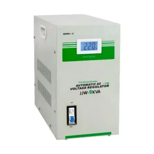
Server racks consuming 30–100 kW per cabinet introduce non-linear loads with high total harmonic distortion (THD). The JJW precise voltage regulator and SJKM3E smart electronic circuit breakers prevent harmonic-induced eddy overheating in secondary neutrals, eliminating nuisance tripping and preserving low power loss under continuous heavy computation cycles.
3. Heavy Metallurgical, Mining & Marine Operations
Harsh operating environments with saline humidity, dust, and continuous mechanical shock demand hermetic insulation. Fully insulated RM6 gas-filled switchgear and S11-M sealed distribution transformers prevent internal atmospheric contamination, keeping contact resistance from oxidizing and mitigating arcing hazards in corrosive operating environments.
EPC Sourcing Guide: Auditing OEM Low Loss Factories
Vetting an original equipment manufacturer (OEM) for critical medium- and low-voltage systems requires looking beyond surface-level catalog claims. Rigorous factory validation guarantees compliance with real-world energy efficiency and safety benchmarks.
Raw Material Metallurgy & Traceability
Verify whether the factory sources grain-oriented electrical steels from tier-1 mills (e.g., Baosteel, Nippon Steel) with verified Epstein test loss certificates. For current-carrying paths, require electrolytic copper certification (Cu-ETP > 99.9% purity) with cross-sectional verification to prevent high resistive bottlenecks in main bus lines.
Accredited Type Test Certification
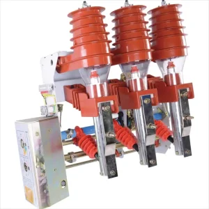
Ensure that all breaker mechanisms (VS1, SJKM3), load break switches (FKRN12), and switchgear enclosures (KYN28-12) carry third-party type test reports from accredited laboratories (e.g., KEMA, CESI, ASTA, or national high-voltage testing centers). Key tests must include short-time withstand current (Ik/tk), internal arc classification (IAC AFLR), and temperature rise verification at rated current.
Factory Acceptance Testing (FAT) Protocols
Tier-1 OEM facilities must maintain precision automated test fields executing 100% routine tests compliant with IEC 60076 (for transformers) and IEC 62271-200 (for switchgear). These tests include power-frequency withstand voltage, winding resistance via micro-ohmmeter bridges, turns ratio and vector group checks, and computerized no-load and load loss loss-measurement tables.
Custom Engineering & Modular Flexibility
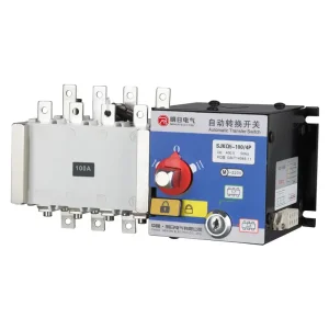
True OEM/ODM partners offer agile customization: adapting switchgear busbar arrangements to existing substation layouts, integrating custom digital protection relays (SEL, ABB, Schneider, or proprietary micro-controllers), and fabricating dual-power ATS transfers (SJKQ5) matched precisely to emergency backup gen-set topologies.
Technology Roadmap: Next-Decade Power Systems (2025–2035)
The convergence of advanced materials science, solid-state semiconductors, and digital intelligence is reshaping the definition of electrical transmission efficiency.
Phase 1: High-Permeability Amorphous & SF6-Free Eco Gases (2025–2027)
Transitioning from traditional SF6 gas insulation to zero-GWP (Global Warming Potential) alternative gas mixtures (fluoronitrile-based gas mixtures, clean synthetic air). Integration of amorphous alloy cores across 10kV–35kV distribution transformers to lower no-load tare power drain below 25% of current standard ceilings.
Phase 2: Solid-State MV Breakers & Wide Bandgap Power Conversion (2028–2031)
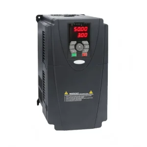
Silicon Carbide (SiC) and Gallium Nitride (GaN) power semiconductors deployed in hybrid solid-state circuit breakers. These provide microsecond interruption times with zero contact erosion, accompanied by high-efficiency frequency converters (MC9001 series) exceeding 99.4% inverting efficiency under dynamic variable speed motor drive conditions.
Phase 3: Autonomous AI Digital Twins & Dynamic Thermal Balancing (2032–2035)
Embedding optical fiber Bragg grating (FBG) temperature sensors and partial discharge acoustic arrays directly inside dry-type transformer windings and switchgear bus interfaces. Machine learning models will compute dynamic ampacity limits in real time, preventing hotspots and optimizing continuous load currents for minimal grid-wide dissipation.
End-to-End Low-Loss Electrical Distribution Topology
True energy conservation is achieved through system-level optimization rather than isolated component selection. A harmonized lineup from incoming medium-voltage switchgear to final motor control centers minimizes compounding cumulative losses.
1. MV Grid Infeed & Substation Protection
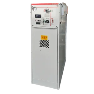
Incoming 12–24 kV feeders connect via withdrawable KYN28-12 metal-clad switchgear equipped with VS1 vacuum breakers or fully sealed RM6 ring main units. Precision air-load break switches (FKRN12) with integrated current-limiting fuses provide rapid short-circuit clearance without system-wide voltage drops, keeping primary distribution losses under strict control.
2. Step-Down Transformation & Voltage Regulation
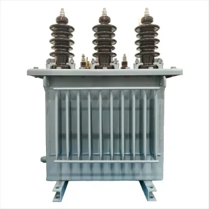
Stepping down from 10kV to 400V using non-encapsulated SG(B)10 or oil-filled S11-M transformers configured for optimal load points (55%–70% loading). Coupled with JJW high-precision voltage stabilization, this stage stabilizes voltage fluctuations to within ±1%, preventing inductive motors and server power supplies from pulling excess reactive currents.
3. LV Sub-Distribution, Motor Control & ATS
Distribution to plant floors via SJKM3/SJKM5 MCCBs and intelligent SJKM3E electronic breakers that prevent branch over-current build-up. Dual power reliability is maintained through rapid-action SJKQ5 automatic transfer switches, while industrial pump and motor lines are driven by MC9001 frequency converters, matching variable kinetic work with real-time motor excitation.
Low Loss Engineering & Sourcing FAQ
Detailed technical answers for EPC electrical engineers, utility procurement directors, and plant managers.
TCO is evaluated using Total Owning Cost capitalization formulas: TOC = Initial Purchase Price + (A × No-Load Loss in Watts) + (B × Load Loss in Watts). The "A" factor calculates the capitalized present value of continuous no-load core losses over the operating life (typically 20–30 years) under utility tariffs, while the "B" factor reflects expected loading cycles and peak demand costs. High-efficiency units like our SG(B)10 or S11-M generally achieve full capital payback within 24 to 36 months of installation through lower utility bills.
While both provide excellent fire safety compared to oil-immersed transformers, non-encapsulated dry-type units (SG(B)10 series) utilize Class H or Class C Nomex insulation materials capable of withstanding operating temperatures up to 180°C–220°C. Non-encapsulated coils have superior thermal dissipation curves, provide exceptional resistance to thermal shock cracking during sub-zero cold starts, and allow higher short-term emergency overload capacities without degradation compared to solid cast resin designs.
Per IEC 62271-1, contact resistance within main circuit breaker poles and disconnectors must remain below specified micro-ohm ratings (typically < 25–40 µΩ depending on rated current). Excessive resistance leads to localized thermal runaway ($P = I^2R$). For example, a 3,150A switchgear panel with an additional 50 µΩ of contact degradation generates nearly 500 Watts of localized heat per pole, degrading silver plating, softening contact springs, and precipitating catastrophic phase-to-phase flashovers.
Yes. While our core product architectures are engineered to IEC standards (such as IEC 62271, 60076, and 60947), our factory provides custom OEM adaptations including dual-frequency (50/60Hz) transformer core sizing, NEMA-standard bus drilling patterns, UL-listed auxiliary components, and ANSI C37-compliant enclosure compartmentalization and racking interlocks upon project specification.
Intelligent Switching, Isolation & Transmission Units
Explore the remainder of our engineered product lineup, featuring vacuum interrupters, gas-insulated switchgear, automated transfer systems, and heavy-duty industrial breakers.