Integrated High-Voltage Apparatus & Core Components
Explore our foundational transmission and distribution equipment manufactured under rigorous ISO 9001 and IEC manufacturing tolerances.
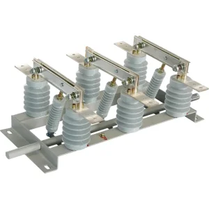
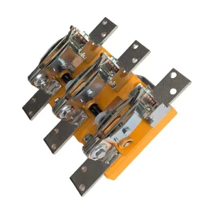
Engineering Architecture of GN30-12(D) Indoor Rotary Disconnector
A comprehensive technological review of high-voltage circuit isolation, contact geometry, mechanical interlocking, and dielectric insulation integrity under extreme load scenarios.
Dual-Blade Rotary Mechanism
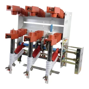
The GN30-12 deviates from conventional linear travel knives by adopting a rotational blade topology. Contacts move within a horizontal or vertical plane around a fixed rotational axis, ensuring zero axial displacement impact on adjacent switchgear busbars while significantly reducing overall panel cubicle volume.
Integrated Grounding ("D" Designation)
The GN30-12D configuration features an integrated lower or upper earthing switch. Engineered with mechanical failsafe interlocks, it strictly guarantees that ground contacts cannot close when main blades are energized, eliminating fatal operational sequencing hazards during busbar maintenance.
Optimized Dynamic Thermal Stability
Fabricated with high-grade T2 electrolytic copper conductors (≥99.95% purity) treated with multi-layer silver electroplating (≥15μm). Electro-dynamic clamping pressures increase proportionally under peak short-circuit surges, completely preventing contact micro-welding up to 125kA peak withstand.
Standardized Parametric Specifications: GN30-12 vs GN30-12(D)
Verified laboratory performance parameters compliant with IEC 62271-102 and GB/T 1985-2014 standards.
| Electrical & Physical Parameters | GN30-12 (Standard Rotary) | GN30-12D (Single Grounding) | GN30-12D (Dual Grounding) |
|---|---|---|---|
| Rated Voltage (Ur) | 12 kV | 12 kV | 12 kV |
| Rated Frequency (fr) | 50 / 60 Hz | 50 / 60 Hz | 50 / 60 Hz |
| Rated Continuous Current (Ir) | 630A, 1000A, 1250A, 1600A, 2000A, 3150A | 630A, 1000A, 1250A, 1600A, 2000A, 3150A | 630A, 1250A, 2000A, 3150A |
| Rated Short-Time Withstand Current (4s) | 25 kA / 31.5 kA / 40 kA / 50 kA | 25 kA / 31.5 kA / 40 kA / 50 kA | 31.5 kA / 40 kA / 50 kA |
| Rated Peak Withstand Current (Ip) | 63 kA / 80 kA / 100 kA / 125 kA | 63 kA / 80 kA / 100 kA / 125 kA | 80 kA / 100 kA / 125 kA |
| Power Frequency Withstand (1 min - Earth & Phase) | 42 kV (Dry test) / 48 kV across isolating distance | 42 kV (Dry test) / 48 kV across isolating distance | 42 kV (Dry test) / 48 kV across isolating distance |
| Lightning Impulse Withstand (BIL) | 75 kV (Peak) / 85 kV across isolating gap | 75 kV (Peak) / 85 kV across isolating gap | 75 kV (Peak) / 85 kV across isolating gap |
| Phase-to-Phase Center Distance | 210 mm / 275 mm / 310 mm | 210 mm / 275 mm / 310 mm | 275 mm / 310 mm |
| Operating Mechanism Compatibility | CS6-2 manual / CS17 manual / Motorized actuator | CS6-2 double linkage / CS17 dual-shaft | CS17 interlocked / Integrated automation link |
Systemic Integration in Turnkey Substation Architecture
How Tier-1 EPC contractors and switchgear original equipment manufacturers optimize panel footprints and busbar configurations using GN30 series disconnectors.
KYN28A-12 & XGN-12 Switchgear Cubicles
In mid-voltage compartmentalized metal-clad switchgear, space optimization determines heat dissipation efficiency. Traditional knife switches require substantial swing clearance, restricting cabling space. The rotary structure of the GN30-12 allows direct placement in the busbar partition, enabling top-and-bottom bus partition isolation while conserving up to 35% cubicle depth.
Renewable Energy Step-Up Substations (Solar PV & Wind)
Solar solar inverters and wind generation strings introduce severe harmonic strains and continuous switching stresses. By utilizing heavy-duty SMC/epoxy cast resin post insulators with exceptional creepage distances (≥20mm/kV or ≥25mm/kV for saline/coastal areas), the GN30-12 withstands persistent UV radiation, high ambient temperature swings, and cyclic condensation.
Electrified Transit & Traction Power Substations
Urban railway transit and metro line substations demand instantaneous line sectionalization and guaranteed physical air-break verification before maintenance crews access third-rail or catenary feeders. The GN30-12D provides visual isolation gaps through front observation windows, working seamlessly with electro-magnetic interlocks to prevent unauthorized entry.
Hyperscale Data Centers & Continuous Production Sites
Semiconductor fabs and mega data centers cannot tolerate accidental arc flashes caused by human operational sequencing errors. Factory-integrated interlocking pins enforce mandatory breaker tripping prior to switch knife disengagement, securing complete zero-load switching reliability under 24/7 load conditions.
Global EPC Supply Chain Evaluation Criteria
A rigorous quality audit framework for sourcing high-reliability GN30-12 isolating switches from Chinese original equipment manufacturers.
Conductive Copper Purity
Verify suppliers utilize pure grade C11000 electrolytic copper rather than recycled alloys. Incoming spectrometer assays must confirm electrical conductivity ≥98% IACS to ensure full rated current carrying without thermal runaway.
Silver-Plating Thickness
Knife blades and contact jaws must undergo vacuum electro-silver plating with micro-thicknesses measured between 15μm and 20μm. This prevents oxidation, maintains contact resistance <45μΩ, and halts degradation across thousands of switching operations.
Epoxy Insulator Quality
Insulators must be cast using automatic pressure gelation (APG) processes under high vacuum to eliminate internal micro-voids. Dielectric loss factor tan δ and partial discharge values must stay strictly below ≤5pC under 1.2 Ur phase voltage.
Independent Lab Type Tests
Global project compliance demands verifiable CNAS, KEMA, or ASTA accredited test certifications confirming full ratings: short-time withstand current (STW), peak dynamic current, lightning BIL impulse, and mechanical endurance tests.
Technological Roadmap: The Evolution of Intelligent Disconnecting Switches
Strategic advancements transitioning medium-voltage disconnectors from manual mechanics into predictive, IoT-monitored substation assets.
Phase 1: Precision Motorized Drive Integration
Elimination of purely manual lever reliance. Factory-mounted motorized drive linkages with high-precision stepping motors facilitate real-time SCADA remote operation, enabling single-click station busbar transfers and automated fault isolation without risking operator safety inside switch rooms.
Phase 2: Wireless Surface Temperature Sensing
Deployment of passive SAW (Surface Acoustic Wave) or micro-powered RF sensors directly embedded onto static and dynamic contact jaw interfaces. Continuous thermal data logging detects microscopic contact degradation and oxidation before localized hot-spotting triggers phase-to-phase flashovers.
Phase 3: AI-Driven Predictive Maintenance & Digital Twins
Coupling motor torque profiles and operating speed curves with edge-AI controllers. Variations in mechanical resistance immediately flag lubrication dry-out, spindle misalignment, or foreign object obstruction, enabling predictive condition-based maintenance (CBM) over scheduled overhauls.
Frequently Asked Questions on GN30-12(D) Isolating Switches
In-depth technical answers addressing operational mechanics, grid specifications, safety interlocks, and engineering compliance.
What is the key engineering distinction between GN30-12 and GN30-12D?
The "D" letter designator denotes an integrated grounding (earthing) switch mechanism. While the standard GN30-12 serves strictly as an open-air circuit break isolating switch, the GN30-12D incorporates either upper, lower, or dual-sided grounding blades mechanically linked to the main drive shaft. This design guarantees foolproof interlocking: the main isolating contacts cannot be engaged while earth blades are closed, and vice versa.
Can the GN30-12 break electric load currents under live operating conditions?
No. Under IEC 62271-102 guidelines, isolating switches are non-load-break apparatuses lacking arc-quenching media or de-ionizing chambers. They must operate only when the circuit is fully de-energized by an upstream vacuum circuit breaker (VCB) or load break switch (LBS). Attempting to open under load results in an uncontained, destructive arc flash.
How does the rotary knife design outperform traditional linear knife switches like GN19-12?
Traditional GN19 linear switches swing outwards, requiring huge vertical and front-to-back clearance envelopes. The GN30 rotary design rotates within its parallel plane, reducing switch compartment depth by up to 35-40%. Additionally, the dual-contact dynamic rotary movement exerts automatic wiping action, scraping away surface oxidation films during each operation cycle.
What environmental derating applies to high-altitude installations (>1000m)?
For installations above 1000 meters sea level, ambient air density reduces dielectric breakdown strength. In accordance with IEC 60071-2, power-frequency and impulse withstand levels must be calculated with altitude correction factors (Ka). For 3000m applications, switchgear manufacturers employ extended creepage post-insulators and wider phase-to-phase clearances (e.g., expanding from 210mm to 275mm or 310mm).
What operating mechanisms are matched with GN30 series isolating switches?
Manual configurations commonly leverage the CS6-2 or CS17 operating mechanism. The CS17 dual-shaft mechanism is specifically configured for GN30-12D variants to coordinate the main knife drive and the earthing blade via separate interlocked levers. Motorized actuators (CJ6 or customized DC24V/DC110V/DC220V/AC220V motorized units) are chosen for automated substations.
How does GN30-12 guarantee electrodynamic stability during severe short circuits?
During an external fault, peak short-circuit currents generate massive electromagnetic forces. The GN30 dual-blade construction places parallel conductor branches in geometric proximity such that electromagnetic repulsion clamps the blades inward against the stationary contact finger, preventing contact separation or micro-arcing precisely when fault currents peak.
Medium & Low Voltage Switchgear, Transformers & Control Solutions
Complementary power transmission apparatus and low-voltage protection units engineered for end-to-end substation reliability.