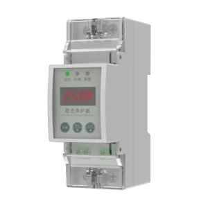
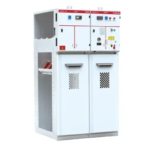
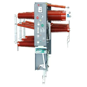
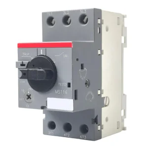
Precision Switchgear, Protection & Overvoltage Components
Integrated power distribution gear manufactured under rigorous ISO 9001 and ISO 14001 quality management protocols in Yueqing, China.
4.5kA SPD Engineering: Sub-Distribution Transient Mitigation
Decoupling overvoltage dynamics, terminal-point clamping, and internal thermal-fuse physics for modern low-voltage installations.
In modern electrical architectures, transient overvoltage mitigation is structured across an impedance-coordinated cascade. While high-capacity Type 1 and Type 2 Surge Protective Devices (SPDs) handle massive current surges (20kA to 100kA) at the main low-voltage service entrance, 4.5kA SPDs fulfill an indispensable role in tertiary and terminal sub-distribution networks. These devices, engineered under IEC 61643-11 Class II and Class III (or UL 1449 Type 2 and Type 3), are designed specifically to arrest secondary transient remnants, inductive switching spikes, and residual atmospheric discharges before they reach mission-critical sensitive loads.
Industrial procurement teams and electrical engineers often define 4.5kA in two primary technical dimensions: the nominal discharge current ($I_n = 4.5\text{kA}$, 8/20 µs waveform) for compact DIN-rail branch modules, and the rated short-circuit interrupting capacity ($I_{cn} / I_{cs} = 4.5\text{kA}$) for integrated SPD-breaker combinations (SCPDs). In both engineering paradigms, achieving precision coordination requires robust metal-oxide varistors (MOVs) paired with fast-acting thermal disconnector springs and heavy-duty gas discharge tubes (GDTs) for galvanically isolated N-PE paths.
Enterprise Sourcing Challenges & Custom OEM/ODM Solutions
Addressing thermal runaway risks, global regulatory divergence, and modular mechanical configurations.
Thermal Disconnect Mechanics
Low-grade SPDs suffer catastrophic failure when continuous micro-leakage causes internal thermal avalanche. Top-tier OEM manufacturers utilize precision low-temperature eutectic solder bridges (melting at 138°C) paired with pre-stressed copper springs to mechanically decouple degraded MOVs within milliseconds, clearing faults before ignition.
Regulatory Dual-Standard Compliance
Global original equipment manufacturers require seamless compliance across divergent regions. Professional Chinese tier-1 suppliers build universal chassis designs certified for both IEC 61643-11 (European CE / CB schemes) and UL 1449 5th Edition (North American cURus), simplifying inventory for multinational switchgear assemblers.
Modular Pluggable Footprints
Downtime in industrial applications is cost-prohibitive. OEM modular designs feature hot-swappable plug-in cartridges with positive keying locks. This allows field technicians to replace depleted MOV cartridges without de-energizing the main terminal busbar or disconnecting wire harnesses.
Comprehensive OEM/ODM Engineering Configuration Options
Leading tier-1 manufacturing partners provide enterprise buyers with granular configuration capabilities to match distinct target markets and enclosure footprints:
- Pole Configurations: 1P, 2P, 3P, 4P, 1P+N, and 3P+N (TT, TN-C, TN-S, and IT grid grounding systems).
- Continuous Operating Voltage ($U_c$): Custom-tuned MOV stacks rated for 150V, 275V, 320V, 385V, 440V, and up to 690V AC, preventing premature aging in volatile grid conditions.
- Telemetry & Signaling: Integrated dry-contact auxiliary micro-switches (Form C: NO/NC) for remote SCADA integration and IoT condition monitoring.
- Chassis Resins & Flame Retardancy: Halogen-free, glass-fiber reinforced PBT/PA66 engineering polymers compliant with UL 94 V-0 flame spread ratings and IEC 60695-2-11 glow-wire tests ($960^\circ\text{C}$).
China Industry 4.0: Yueqing Supply Chain Resilience & Quality Control
How the world's most concentrated low-voltage electrical manufacturing hub delivers uncompromising quality and economies of scale.
Located in Zhejiang Province, the Yueqing electrical industrial cluster represents the epicenter of global low-voltage component manufacturing. Companies like Mingri Electric utilize a tightly integrated regional ecosystem where raw materials, precision stamping, automated silver-soldering, and certified test laboratories operate within a 15-kilometer radius. This geographic synergy drives unmatched cost efficiencies, compressed lead times, and continuous product iteration.
Automated MOV Laser Binning
Varistor disc quality dictates SPD longevity. Factory 4.0 lines deploy automated classification robotics that test 100% of incoming zinc oxide (ZnO) varistor discs under 1mA DC reference voltage ($U_{1mA}$) and leakage current ($I_L \le 20\mu\text{A}$), binning components to tight ±3% tolerances to eliminate internal parallel current imbalances.
Multi-Stage Impulse Verification
Every mass-produced OEM module undergoes multi-stage digital testing. Automated test stations subject completed sub-assemblies to calibrated 8/20 µs combination wave surges, verifying residual voltage clamping limits, mechanical flag ejection, and circuit continuity in real-time execution.
End-to-End Traceability (MES)
Each unit is laser-engraved with an immutable 2D DataMatrix code linked to the Manufacturing Execution System (MES). From raw powder batch sintering records to final assembly torque and hipot dielectric testing, overseas EPC buyers receive auditable pedigree tracking for every production lot.
Global Grid Transformation & 4.5kA Sub-Protection Demand
The electrification of transport, microgrid growth, and edge electronics drive exponential growth in terminal surge suppression.
The global surge protection device market is undergoing structural expansion driven by three critical industrial transitions: the integration of distributed renewable power, the widespread installation of electric vehicle (EV) charging infrastructures, and the ubiquitous deployment of smart industrial Internet of Things (IIoT) sensors. While legacy infrastructure primarily protected heavy motor loads, contemporary operations depend upon microprocessor-based controllers operating at ultra-low logic voltages (3.3V to 24V DC).
Smart Metering & AMR
Advanced Metering Infrastructure (AMI) deployed across urban electrical grids requires rugged, compact 4.5kA SPDs within meter distribution cabinets to protect against switching transients from inductive capacitor banks.
EV Fast Charger Sub-Circuits
DC fast charging stations incorporate sophisticated control PCBs, payment gateways, and RFID readers. 4.5kA Type 2/3 SPDs protect internal low-voltage auxiliary power supplies from inductive switching spikes caused by high-power IGBT switches.
Telecom & 5G Small Cells
Compact outdoor 5G small cells and Remote Radio Heads (RRHs) demand extreme space optimization. 18mm DIN-rail footprint 4.5kA protectors deliver localized transient dissipation under harsh tropical lightning exposures.
Industrial PLC Racks
Programmable Logic Controllers and I/O slices in process manufacturing face damaging common-mode transients from nearby VFDs and magnetic starters. Point-of-use 4.5kA SPDs preserve plant uptime.
Technical Specification & Cascading Coordination Matrix
Comparative design parameters for proper coordination between upstream Class I/II and downstream 4.5kA protection tiers.
| Specification Parameter | Service Entrance (Type 1) | Main Distribution (Type 2) | Sub-Distribution / Terminal (4.5kA Class II/III) |
|---|---|---|---|
| Target Standard | IEC 61643-11 Class I / UL 1449 Type 1 | IEC 61643-11 Class II / UL 1449 Type 2 | IEC 61643-11 Class II & III / UL 1449 Type 3 |
| Discharge Waveform | 10/350 µs direct lightning wave | 8/20 µs induced surge wave | 8/20 µs & 1.2/50 µs combination wave |
| Nominal Discharge ($I_n$) | 25 kA – 50 kA / pole | 20 kA – 40 kA / pole | 4.5 kA – 5 kA / pole |
| Maximum Discharge ($I_{max}$) | 50 kA – 100 kA / pole | 40 kA – 80 kA / pole | 10 kA – 15 kA / pole |
| Voltage Protection Level ($U_p$) | ≤ 2.5 kV | ≤ 1.8 kV – 2.0 kV | ≤ 1.0 kV – 1.2 kV |
| Response Time ($t_A$) | < 100 ns (Spark Gap) / < 25 ns (MOV) | < 25 ns | < 25 ns (Ultra-fast clamping) |
| Typical Form Factor | Heavy-duty modular panel (36mm/pole) | Standard DIN-rail (18mm/pole) | Slimline DIN-rail (9mm–18mm) / In-line PCB |
| Primary Installation Site | Main Switchboard (MSB) / Transformer LV | Sub-Distribution Boards (SDB) | Final Branch Consumer Units, PLC Racks, LED Drivers |
Engineering Sizing Note: When designing a coordinated electrical protection plan, maintain sufficient electrical decoupling between stages. If the physical wiring distance between the upstream 40kA Type 2 SPD and the 4.5kA terminal SPD is less than 5 meters, an in-line decoupling inductor ($L \approx 15\mu\text{H}$) must be specified to prevent the downstream device from prematurely absorbing high-energy lightning currents meant for the primary stage.
Frequently Asked Questions on 4.5kA SPD OEM Manufacturing & Sourcing
Detailed technical, compliance, and supply chain insights for global procurement engineers.
What is the explicit difference between a 4.5kA nominal discharge ($I_n$) SPD and a 4.5kA breaking capacity ($I_{cn}$) breaker-SPD combo?
Nominal discharge current ($I_n = 4.5\text{kA}$, 8/20 µs) indicates the peak impulse current the surge arrester can divert safely at least 15 to 20 consecutive times without suffering dielectric breakdown or parameter drift. Conversely, a 4.5kA short-circuit breaking capacity ($I_{cn}$ / $I_{cs}$ under IEC 60898-1) refers to an integrated Miniature Circuit Breaker (MCB) combined with surge protection that can clear an AC short-circuit fault of 4,500 amperes at 230/400V without mechanical destruction or contact welding. OEM purchasers must clarify whether their requirement pertains to impulse surge handling or short-circuit overcurrent clearing.
Why is a 4.5kA SPD chosen over a 20kA or 40kA device in sub-distribution panels?
Selecting a 4.5kA SPD is governed by precision clamping voltage ($U_p$), spatial footprint, and bill-of-materials economics. While a 40kA SPD uses larger varistor discs, its residual clamping voltage is frequently higher ($1.8\text{kV}$ to $2.2\text{kV}$), which does not adequately protect sensitive solid-state microcontrollers requiring $U_p \le 1.0\text{kV}$ to $1.2\text{kV}$. A 4.5kA Class III/II device features lower clamping thresholds, compact DIN dimensions (as thin as 9mm or 18mm single-slot), and optimized internal capacitance for branch automation panels.
How does an OEM factory prevent thermal runaway in compact 4.5kA SPD modules?
Thermal runaway occurs when aging MOVs pass continuous milliampere leakage current under nominal AC operating voltage. Advanced OEM factories integrate dual-action thermal protection: (1) a calibrated micro-solder joint placed in direct mechanical contact with the varistor face, which melts under abnormal temperatures and is instantly pulled clear by a high-tension spring, and (2) an arc-insulating barrier that slides between the disconnected contacts to prevent continuous fault arcing and fire hazard.
What backup overcurrent protection (fuse or circuit breaker) must be paired with a 4.5kA SPD?
Under IEC 61643-11 clause 7.7.3, every SPD installation must incorporate Dedicated Overcurrent Protection (DOCP) or a coordinated backup fuse unless the upstream circuit breaker already satisfies the manufacturer's maximum backup rating (typically 16A to 32A gG/gL fuses for 4.5kA SPDs). The fuse must be sized high enough to avoid nuisance blowing during nominal 4.5kA 8/20 µs impulses, but low enough to clear power-frequency short circuits if the SPD suffers end-of-life short-circuit failure.
Can OEM suppliers customize 4.5kA SPDs for DC solar and battery storage systems?
Yes. Direct-current applications introduce severe extinguishing challenges because DC voltage lacks a natural zero-crossing point. For DC photovoltaic or battery energy storage circuits, OEM manufacturers configure 4.5kA DC SPDs with integrated high-energy magnetic arc chutes, specialized DC-rated MOVs, and series disconnectors to reliably clear DC arcs up to 1000V or 1500V DC without sustained conduction.
What documentation should global procurement teams require during factory technical audits?
Enterprise buyers should request: (1) Type Test Certificates issued by accredited third-party laboratories (such as KEMA, DEKRA, TÜV, or Intertek) validating compliance with IEC 61643-11 or UL 1449; (2) ISO 9001, ISO 14001, and ISO 45001 management system records; (3) Raw material traceability reports, particularly for varistor ceramic discs and copper alloys; and (4) Internal Factory Acceptance Test (FAT) impulse log files recorded by automated test benches.
High-Performance Switching, Control & Substation Gear
Explore complementary OEM/ODM products engineered for complete power transmission, distribution, and equipment protection.