Reading a Ring Main Unit Sld is not a paperwork exercise. It is a practical safety skill. The drawing shows how medium-voltage power enters, travels, switches, and exits the network. One incorrect symbol can hide an open point, an earth switch, or an unexpected backfeed. That matters in a substation room filled with steel panels, warning labels, and cables disappearing below the floor.
Power-distribution engineer H. Lee Willis is widely respected for his technical writing. His practical reminder is worth keeping in mind: “A diagram is only useful when it matches the equipment in front of you.” The wording may sound simple. The discipline is not. Compare the SLD with the nameplate, cable tags, protection settings, and operating position. Do not trust a clean drawing blindly.
This guide presents seven focused tips for reading a Ring Main Unit Sld with greater confidence. It explains feeder paths, busbar connections, circuit-breaker symbols, load-break switches, earthing points, interlocks, and protection devices. It also highlights details that inexperienced readers often miss, such as normally open points and transformer incomers. Some diagrams remain unclear, even after careful inspection. That is a useful warning, not a failure. When symbols conflict with site conditions, stop and verify the latest approved drawing with a qualified engineer. A red pen, a flashlight, and patient checking can prevent a serious misunderstanding.
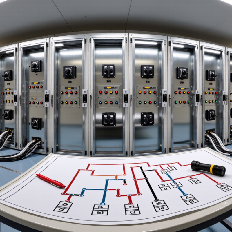
An RMU single-line diagram represents a three-phase network with one line. Read it as a power path, not as a physical layout. The incoming cable usually reaches a ring switch, then connects to the busbar. A second ring switch continues the feeder. Trace it slowly. The busbar is often shown as a thick horizontal line, while cable connections appear as short vertical drops. Labels such as IN, OUT, and T indicate the feeder direction and transformer connection.
Common symbols identify the operating equipment. A switch-disconnector controls load current but may not clear every fault. A circuit breaker can interrupt fault current and usually works with a protection relay. An earthing switch connects an isolated section to ground; its ground symbol is easy to overlook. Fuses may appear beside a transformer feeder, while current transformers can be marked as small rings around the conductor. Check the drawing legend.
In field drawing reviews, the most serious error is assuming a symbol shows the live condition. It may only show the intended arrangement. Open and closed contacts, interlocks, and cable labels require careful checking. Do not guess. Compare the SLD with the equipment nameplate, termination schedule, and approved revision. Protection settings, transformer ratings, and feeder identifiers should agree across documents. A missing earth connection or unclear switch position deserves a question before operation. Even experienced readers can miss a small auxiliary contact. That is why a second review remains useful.
When reading a ring main unit (RMU) single-line diagram, I trace power with a pencil before studying every symbol. Start at the incoming cable and follow its line into the cable compartment. Check the incoming switch, circuit-breaker, or load-break switch. Then locate the busbar, shown as the common horizontal path. Read the legend carefully. Symbols can vary between drawings.
Follow the busbar toward the outgoing feeder. This path usually leads through another switching device, protection equipment, and an outgoing cable. Confirm whether the feeder supplies a transformer, distribution board, or another RMU. Watch the arrows. Some diagrams show normal power flow, while others show possible ring directions. The route may look simple.
Seven practical checks improve accuracy: identify voltage levels, mark each source, trace both ring ends, locate earth switches, inspect interlocks, confirm protection points, and compare cable labels with field markings. Keep the drawing beside the equipment. Never rely on line position alone. An earth switch may appear close to a feeder but remain electrically separate. I have seen rushed readings miss this detail. That mistake deserves reflection.
Check whether the incoming and outgoing switches can close simultaneously. Review the operating sequence and isolation points using approved procedures. A diagram is useful evidence, not permission to operate equipment. Verify its revision, and confirm conditions with qualified personnel before any switching activity.
Use the single-line diagram to follow power from the 11 kV incoming feeder through the RMU busbar and into each outgoing feeder. The chart shows representative three-phase current and calculated apparent power for a typical 11 kV RMU arrangement. Apparent power is calculated as √3 × voltage × current.
7 Tips for Reading a Ring Main Unit SLD
Reading a ring main unit single-line diagram begins with the switching devices, not the cables. Each symbol represents a specific function in the medium-voltage circuit. A circuit breaker interrupts fault current. A load-break switch controls normal load current. A disconnector provides visible isolation, but it should not open heavy fault current. An earth switch connects an isolated section to ground for safe maintenance.
Focus on the operating state beside each device. “Closed” usually means the primary path is continuous. “Open” means current cannot pass through that switching point. “Earthed” indicates a deliberate connection to ground, often shown on an outgoing feeder. These states must be read together, not separately. A feeder can appear open while its earth switch remains closed. That detail changes the safety condition completely.
Trace the ring from one incoming feeder to the other, following every switch and cable section. Compare the SLD with the unit’s mimic panel, position indicator, and approved switching schedule. A local indicator may show mechanical position, while the SLD may show the planned network state. They are not always identical. The diagram can be accurate and still incomplete. I have seen readers miss an earth symbol because they followed cable lines too quickly. Slow down at every interlock. If an indication conflicts with the drawing, stop and verify the equipment condition through authorized procedures. Never assume a switch is safe merely because its symbol looks open.
Use the single-line diagram (SLD) to identify each switching device, understand its normal operating position, and confirm the safe isolation path. Symbol conventions may vary, so always check the drawing legend and approved operating procedure.
| Tip | What to Identify | Typical SLD Representation | Normal Operating State | How to Read the State | Key Verification Point |
|---|---|---|---|---|---|
| 1 |
Incoming Ring Switch The switching device that connects an incoming ring cable to the RMU busbar. |
A switch symbol placed between the incoming cable termination and the busbar. | Normally closed | A continuous switch line or closed contact usually indicates that the incoming circuit is connected. | Confirm the cable designation, source direction, and whether the switch is a load-break switch or another approved switching device. |
| 2 |
Outgoing Ring Switch The switch that continues the ring circuit to the next substation or distribution point. |
A second switch symbol connected from the RMU busbar to the outgoing ring cable. |
Normally closed It may be normally open at a normally open point to control load flow. |
Trace the cable from the RMU to the next network section rather than assuming that every ring switch is closed. | Check the network operating plan, feeder labels, and the designated normally open point before changing state. |
| 3 |
Transformer Feeder Device The switching and protection path supplying the transformer. |
A feeder branch from the busbar leading to a transformer symbol, often through a switch-fuse combination or circuit breaker. | Closed when the transformer is energized | Follow the branch from the busbar to the transformer. Do not confuse a feeder switch with the transformer low-voltage main device. | Confirm the protection type, fuse or breaker rating, transformer identification, and whether the transformer is intended to be in service. |
| 4 |
Circuit Breaker A protective switching device capable of interrupting fault current within its rating. |
Commonly shown as a breaker symbol with an associated protection or trip indication. |
Closed during normal service Open after a trip or isolation operation |
Look for separate indications for the main contacts, trip status, spring or mechanism status, and protection relay operation. | An open breaker does not by itself prove that the cable or downstream equipment is dead; isolation and voltage verification are still required. |
| 5 |
Disconnector or Isolator A device used to provide visible or defined isolation when current interruption is not required. |
A switch symbol identified separately from the circuit breaker or load-break switch. |
Closed in service Open for isolation |
Read the open gap or position indication shown on the SLD. A disconnector is not automatically a fault-interrupting device. | Verify that the circuit is unloaded or already interrupted by the correct device before operating the disconnector. |
| 6 |
Earthing Switch A device that connects an isolated cable or equipment section to earth for maintenance safety. |
A switch symbol leading from the circuit conductor to the earth symbol. |
Normally open during service Closed only after approved isolation |
The earth symbol and the switch blade position show whether the isolated section is connected to earth. | Confirm all possible sources are isolated, prove dead using an approved method, and check for interlocks before closing the earthing switch. |
| 7 |
Interlocks, Indicators, and Operating Sequence The logic that prevents unsafe combinations of switching states. |
Mechanical interlock symbols, key interlocks, electrical permissives, position indicators, and alarm or trip annotations. | The service path is connected while the associated earthing switch remains open. | Read the SLD together with the operating-state table. A switch position may be shown as open, closed, tripped, isolated, or earthed. | Follow the approved sequence: identify the circuit, open the load-interrupting device, isolate, verify absence of voltage, apply earth where required, and secure the work area. |
Reading a ring main unit single-line diagram (SLD) requires more than following lines. I check the power path, switching points, protection devices, metering transformers, and earth connections together. The U.S. Energy Information Administration reported 8.9 hours of average interruption time per customer in 2023, including major events. Clear protection and earthing logic therefore matters.
Tip 1: Trace the incoming feeder first. Confirm every cable enters the correct circuit breaker or load-break switch.
Tip 2: Identify the fault-clearing device. A fuse symbol suggests different coordination from a relay-controlled breaker.
Tip 3: Check CT ratios, polarity, and relay inputs. A reversed CT can make protection operate incorrectly.
Tip 4: Read the metering circuit separately. CTs measure current, while VTs measure voltage. Do not assume both exist.
Tip 5: Locate the earthing switch and its connection to the earth bar. IEC 62271-200 requires suitable internal arc and segregation considerations for applicable medium-voltage assemblies.
Tip 6: Follow mechanical and electrical interlocks. The SLD should prevent closing an earth switch onto an energized feeder.
Tip 7: Compare the drawing with the physical panel. CIGRE reliability studies repeatedly identify maintenance and human factors as important contributors to network failures.
My own review habit is imperfect: I sometimes trust neat drawings too quickly. Cable labels, test links, and temporary earth points deserve a second look. A small omission can change the entire safety assumption.
Verify the SLD against the physical ring main unit before trusting any switching plan. The International Energy Agency’s Electricity Grids and Secure Energy Transitions report estimates that 80 million kilometres of grids must be added or refurbished by 2040. Aging equipment makes drawing accuracy critical. Stand beside the enclosure. Trace every cable, feeder, earth switch, and interlock shown on the single-line diagram. Do not guess.
Check the RMU nameplate, equipment labels, and cable destinations. Compare rated voltage, short-time withstand current, protection settings, and transformer ratings with the SLD. IEC 62271-200:2021 provides the framework for medium-voltage metal-enclosed switchgear. It also highlights internal-arc classification and compartment design. These details cannot be confirmed from symbols alone. Open the wrong panel, and the diagram becomes dangerous.
I have seen drawings that looked complete but missed a later feeder extension. That is an uncomfortable lesson. Stop there. Photograph discrepancies under approved site procedures, then record them in the redline revision.
CIGRE technical guidance on switchgear condition assessment stresses accurate asset records, inspection history, and consistent field data. Check the cable phase identification and earth continuity physically, not only on paper. A clean SLD can still be obsolete. Have an authorized engineer independently verify isolation points, backfeed paths, and interlocks before any switching activity.
It represents a three-phase network using one simplified line. Read it as a power path, not a physical layout. The diagram shows connections, switching devices, feeders, and equipment functions.
Start at the incoming cable. Follow it to the ring switch, then to the busbar. Continue toward the outgoing switch and cable. Use a pencil. It helps.
The busbar often appears as a thick horizontal line. Cable connections may appear as short vertical drops. Labels such as IN, OUT, and T show feeder direction or transformer connections.
A circuit breaker can interrupt fault current. It usually works with protection equipment. A load-break switch controls normal load current but may not clear every fault.
An earth switch connects an isolated circuit section to ground. Its symbol may appear near a feeder. Check carefully. A feeder can look open while its earth switch remains closed.
“Closed” usually means the primary path is continuous. “Open” means current cannot pass through that point. “Earthed” shows a deliberate ground connection. Read these states together.
Compare the diagram with the equipment nameplate, termination schedule, switching schedule, and approved revision. Cable labels, protection settings, and ratings should agree. Small differences matter.
No. A diagram shows an intended or planned condition. It does not replace field verification or approved procedures. Confirm indicators, interlocks, and equipment condition with qualified personnel.
Do not rely on line position alone. An earth switch may look connected but remain electrically separate. I might miss a small auxiliary contact too. A second review is worthwhile.
Stop and verify the actual condition through authorized procedures. Check the approved revision and operating sequence. Never assume an open symbol proves safe isolation. Slow down.
Understanding a Ring Main Unit Sld becomes much easier when you approach it systematically. Begin by identifying the main components and standard symbols, including incoming and outgoing feeders, busbars, circuit breakers, load-break switches, fuses, transformers, and earth connections. Then trace each power path through the diagram to understand how electricity enters, moves through, and leaves the ring. Pay close attention to switching devices and their indicated operating states, since these symbols show whether a circuit is open, closed, isolated, or earthed.
Next, interpret the protection, metering, and earthing connections to see how the system is monitored, controlled, and protected during normal operation or faults. Finally, compare the SLD with the physical Ring Main Unit by checking equipment labels, cable routes, switch positions, and termination points. This step-by-step verification helps identify discrepancies, improves operational understanding, and supports safer inspection, maintenance, and fault diagnosis.